
2 layers130 × 80 mm

 kcaisley/frida13
📸 ADCs for faster image sensors
Frida65A is an open-source printed circuit board by kcaisley, from the kcaisley/frida repository on GitHub, published under the BSD-3-Clause licence. It is a 4-layer board of 100 × 100 mm with 105 parts on 76 nets, routed with 878 tracks and 128 vias.
It is built around the BAV99. Its parts include 36 resistors, 34 capacitors, 15 connectors, 3 ICs and 2 diodes. It belongs with the sensors and measurement boards of this library.
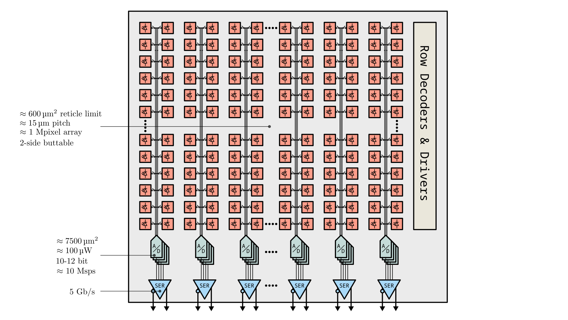
This project focuses on improving analog to digital converters (ADCs) in CMOS image sensors, the chip design discipline with arguably the most stringent constraints on silicon design density. A design flow built on open source EDA tools enables comparison across different circuit topologies and process nodes including 180, 130, 65, and 28 nm. So far, we've fabricated a prototype ASIC in 65 nm using this methodology, which targets a state-of-the-art 2500 µm² area and 100 µW power budget, with a performance of 12-bit resolution at 10 Msps performance.
Frame-based radiation detectors with integrating front-ends are especially well-suited for applications like electron microscopy and X-ray imaging, where hit rates are high and spatial resolution should be maximized with simple pixels. This project also pursues a single-reticle array larger than 1 Mpixel with a continuous frame rate above 100,000 fps. To meet those array-level goals, the converter fabric must deliver aggregate throughput above 1000 Gbps while staying within a 1 W/cm² chip-bottom power-density budget and exceeding 5 ksps/µm² sampling-rate density. Successive-approximation ADCs are the primary architecture under study.
[!NOTE] FRIDA is still under active development. The repository is useful as a record of the design and flow, but it is not yet advertised as reproducible on other people's machines.
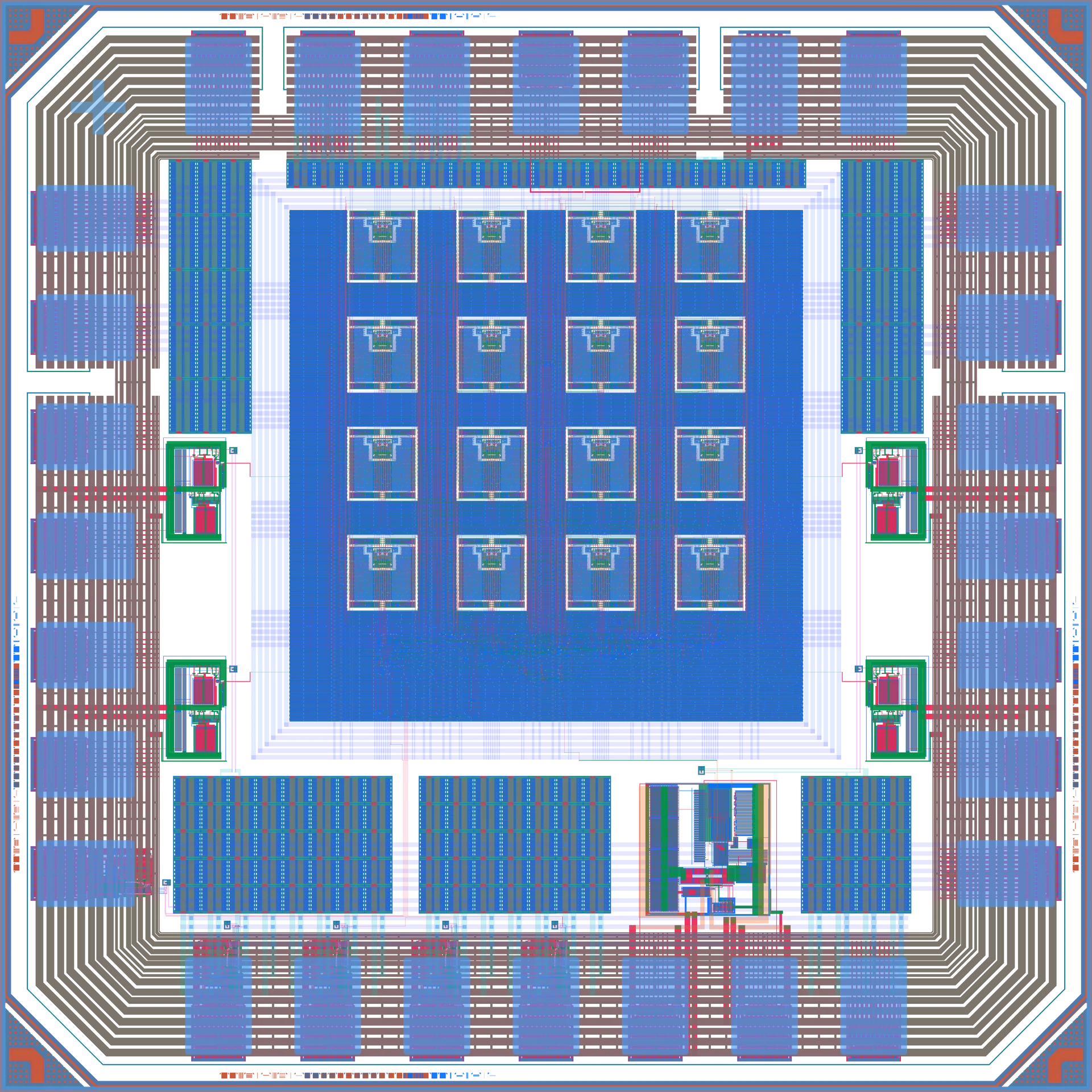
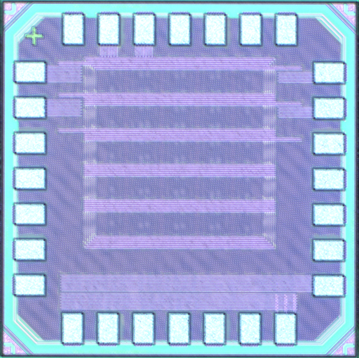
The initial prototype is designed in 65 nm and measures 1 × 1 mm. It contains 16 ADCs. The tapeout was submitted in October 2025, received March 2026, and is currently being characterized.
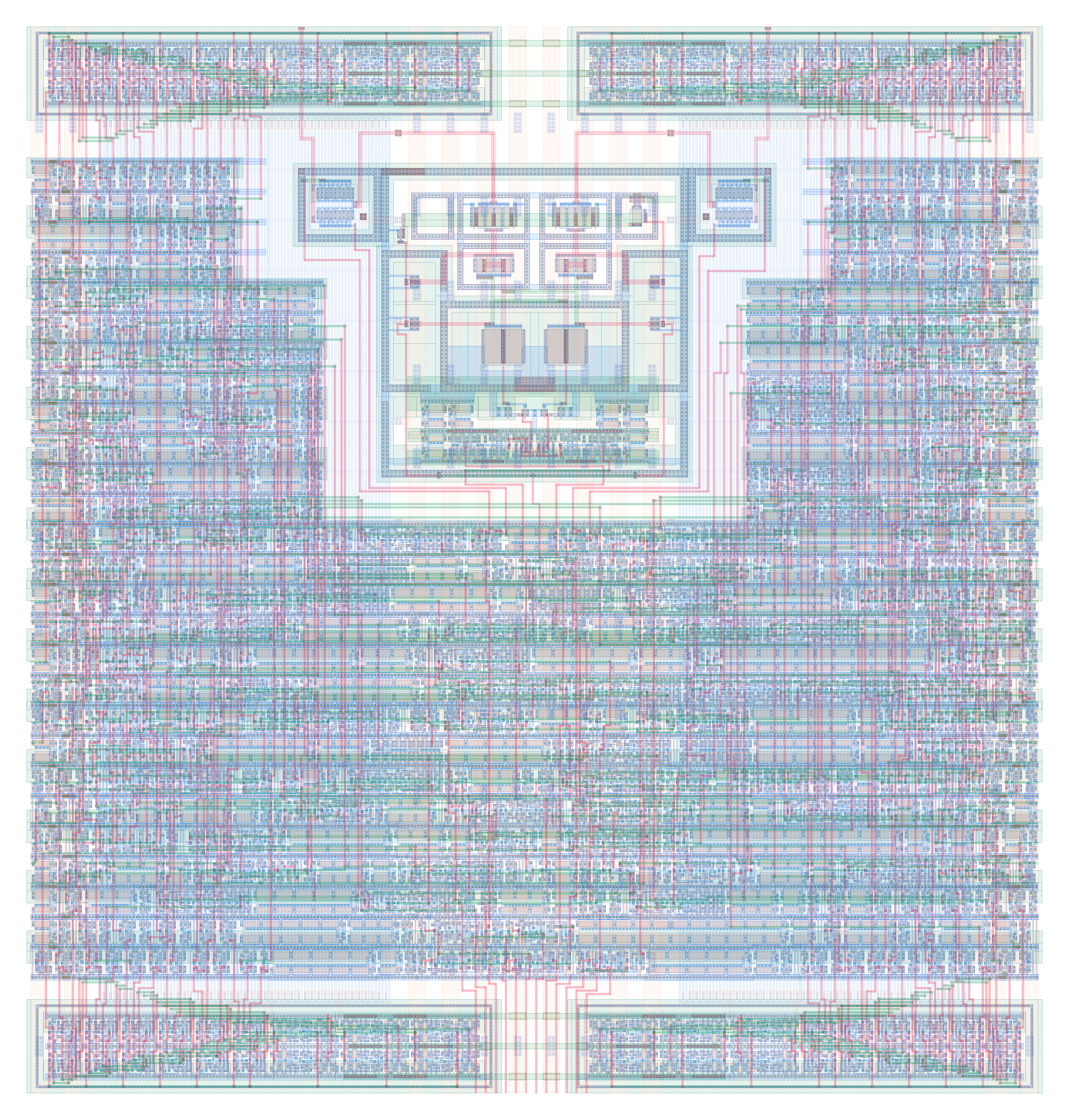
The fabricated FRIDA-1 ADC channel measures approximately 60.5 × 63.5 µm (about 3845 µm²):
The full FRIDA-1 chip, containing 16 ADC channels on a 1 × 1 mm die:
A micrograph of the fabricated prototype:
And the single-chip carrier test card, with wirebonded FRIDA ASIC:
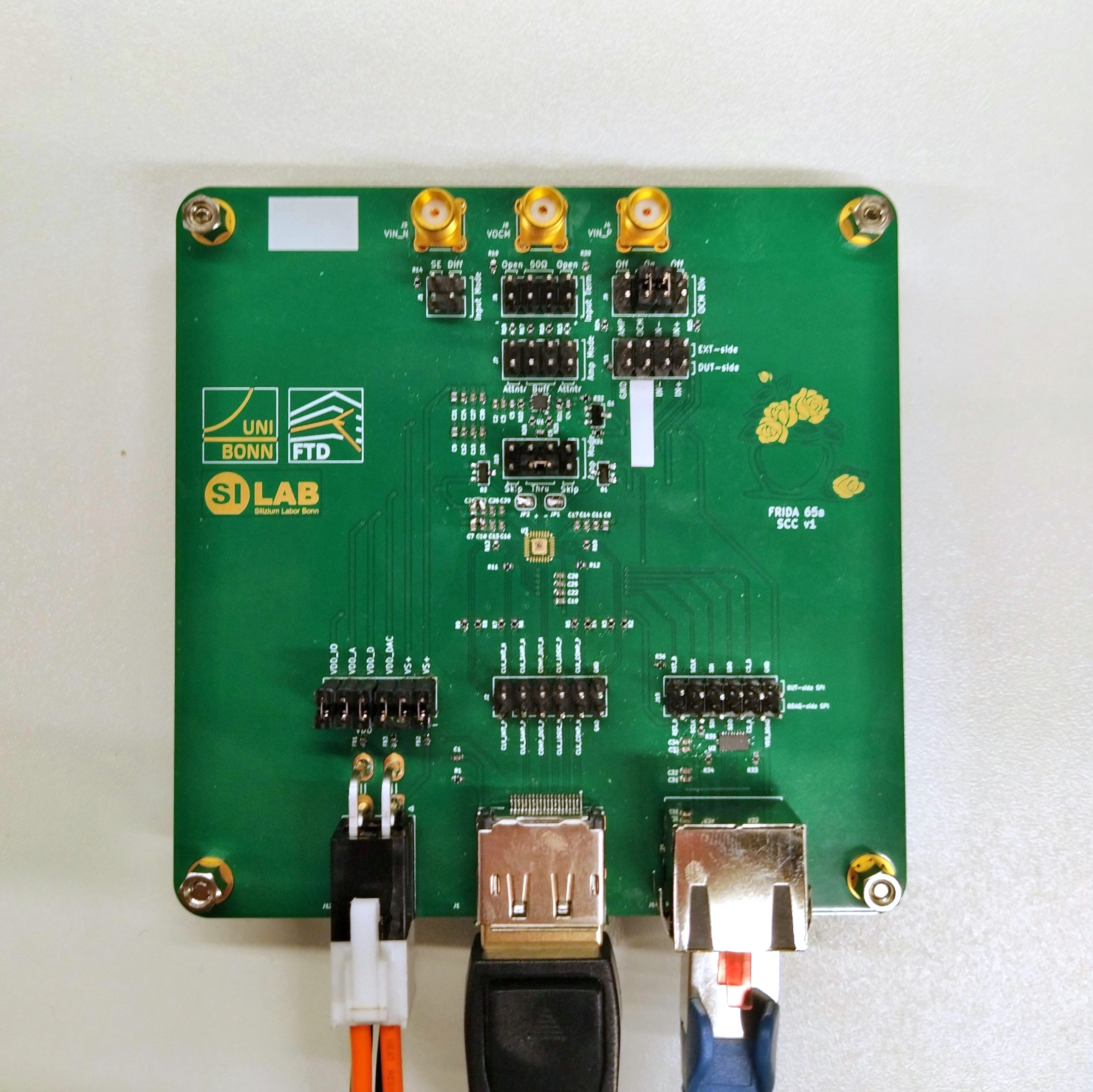
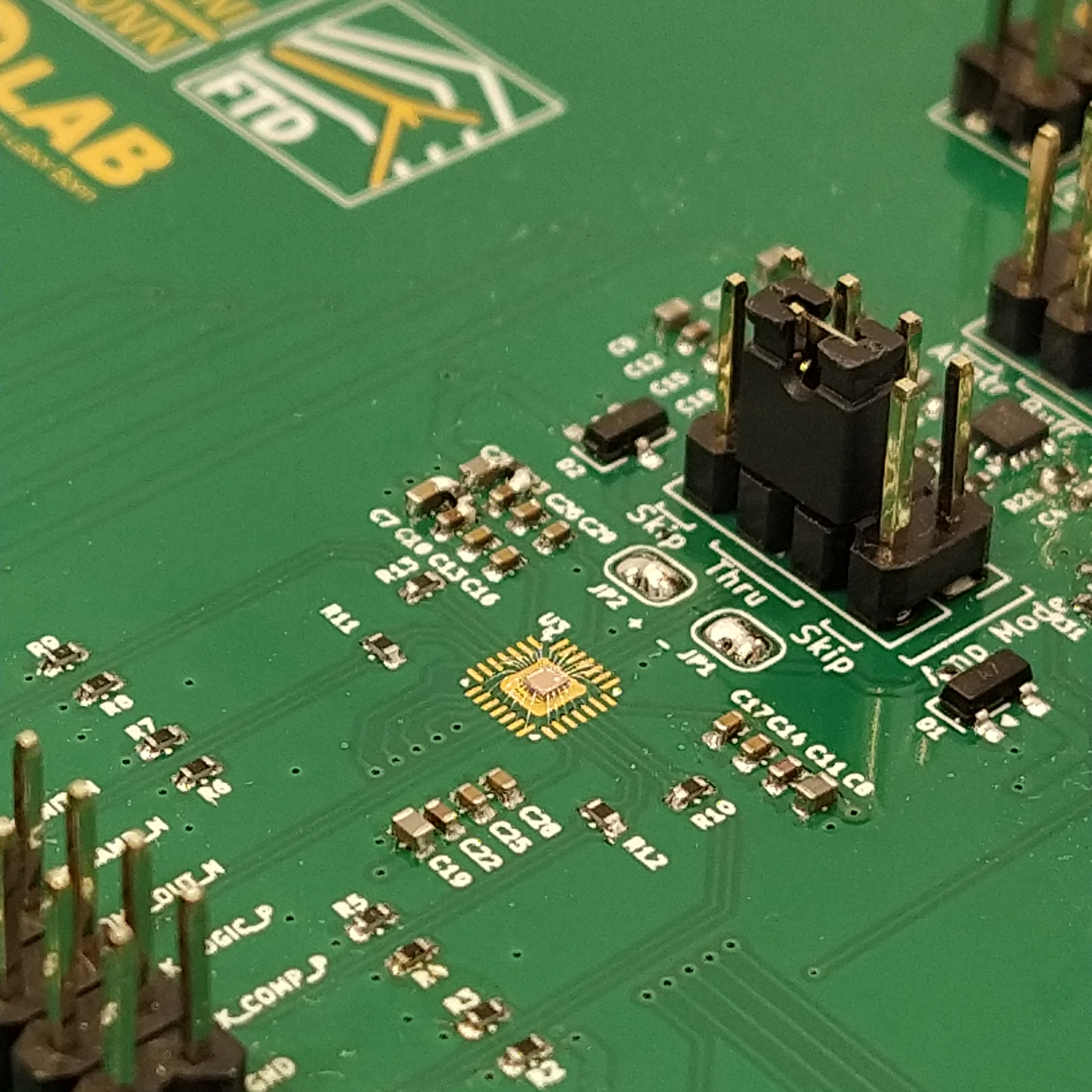
Detailed command-line usage, build notes, and tool installation instructions are recorded in docs/usage.md.
The table below compares previous ADC designs with the current FRIDA target, highlighting improvements in resolution, speed, area, and energy efficiency. Notable advancements include higher conversion rates and lower power consumption per ADC, supporting the project's goal of scalable, high-performance digitizer arrays. The FRIDA column lists design targets; its 50 × 50 µm footprint is smaller than the fabricated FRIDA-1 channel shown above.
| Design | DCD-E | CoRDIA | M | H | FRIDA (this repo) |
|---|---|---|---|---|---|
| Design resolution | 8-bit | 10-bit | 8-bit | 10-bit | 12-bit |
| ENOB | 8.3 | 8.8 | 8.0 | 9.5 | 11.0 (?) |
| Conversion rate | 6.25 MHz | 2.5 MHz | 4.5 MHz | 10 MHz | 10 MHz |
| Dimensions of one ADC | 40×55 μm² | 80×330 μm² | 60×800 μm² | 15×100 μm² | 50×50 μm² |
| Area of one ADC | 0.002 mm² | 0.026 mm² | 0.048 mm² | 0.0015 mm² | 0.0025 mm² |
| Power of one ADC | 960 μW | 30 μW | 700 μW | 100 μW ? | 200 μW ? |
| FOM_csa (conv/sec/area) | 3125 Hz/μm² | 95 Hz/μm² | 105 Hz/μm² | 5000 Hz/μm² | 5000 Hz/μm² |
| FOM_wal (J/conv-step) | 487 fJ | 26 fJ | 608 fJ | 14 fJ | 10 fJ |
| Qty | Value | Footprint | References |
|---|---|---|---|
| 16 | 100n | Capacitor_SMD:C_0402_1005Metric | C1, C3, C13, C14, C15, C16, C17, C18, C25, C26, C27, C28, C29, C30, C32, C33 |
| 10 | 1k | Resistor_SMD:R_0402_1005Metric | R2, R3, R4, R5, R6, R7, R8, R9, R23, R24 |
| 9 | 1u | Capacitor_SMD:C_0402_1005Metric | C2, C10, C11, C12, C22, C23, C24, C31, C34 |
| 7 | 10k | Resistor_SMD:R_0402_1005Metric | R1, R31, R32, R33, R34, R35, R36 |
| 6 | 47u | Capacitor_SMD:C_0402_1005Metric | C7, C8, C9, C19, C20, C21 |
| 6 | 499 | Resistor_SMD:R_0402_1005Metric | R16, R17, R21, R22, R25, R26 |
| 4 | 100 | Resistor_SMD:R_0402_1005Metric | R10, R11, R12, R13 |
| 4 | DNP | Resistor_SMD:R_0201_0603Metric | R27, R28, R29, R30 |
| 4 | MountingHole_Pad | MountingHole:MountingHole_3.2mm_M3_Pad_Via | H1, H2, H3, H4 |
| 3 | 51pF | Capacitor_SMD:C_0402_1005Metric | C4, C5, C6 |
| 3 | FerriteBead_Small | Resistor_SMD:R_0402_1005Metric | FB1, FB2, FB3 |
| 3 | SMA Molex 733910070 | frida:Molex_SMA_733910070 | J3, J4, J8 |
| 2 | 54.9 | Resistor_SMD:R_0402_1005Metric | R19, R20 |
| 2 | BAV99 | Package_TO_SOT_SMD:SOT-23 | D1, D2 |
| 2 | CFG CLAMP | Jumper:SolderJumper-2_P1.3mm_Open_RoundedPad1.0x1.5mm | JP1, JP2 |
| 2 | DNP | Resistor_SMD:R_0402_1005Metric | R15, R18 |
| 2 | TERM CFG | Connector_PinHeader_2.54mm:PinHeader_2x04_P2.54mm_Vertical | J6, J9 |
| 1 | Package_TO_SOT_SMD:SOT-23-3 | Q1 | |
| 1 | 50 | Resistor_SMD:R_0402_1005Metric | R14 |
| 1 | ASIC FRIDA 65A | frida:FRIDA_ASIC_Pad | U3 |
| 1 | ATTEN CFG | Connector_PinHeader_2.54mm:PinHeader_2x04_P2.54mm_Vertical | J7 |
| 1 | DIFF/SE CFG | Connector_PinHeader_2.54mm:PinHeader_2x02_P2.54mm_Vertical | J5 |
| 1 | DiffAmp TI THS4541 | frida:TI_DiffAmp_THS4541 | U1 |
| 1 | DisplayPort Molex 472720024 | frida:Molex_DisplayPort_472720024 | J1 |
| 1 | LOGO | frida:SiLab Logo | G*** |
| 1 | LOGO | frida:final | G*** |
| 1 | LOGO | frida:UBonn Logo | G*** |
| 1 | MiniFitJr Molex 469990014 | frida:Molex_MiniFitJr_469990014 | J12 |
| 1 | POWER | Connector_PinHeader_2.54mm:PinHeader_2x06_P2.54mm_Vertical | J13 |
| 1 | RJ45 Molex 446200002 | frida:Molex_RJ45_446200002 | J14 |
| 1 | SPI TP | Connector_PinHeader_2.54mm:PinHeader_2x06_P2.54mm_Vertical | J15 |
| 1 | TI LevelShifter SN74AXC8T245RJWR | frida:TI_LevelShifter_SN74AXC8T245RJWR | U2 |
| 1 | TP AMP | Connector_PinHeader_2.54mm:PinHeader_2x04_P2.54mm_Vertical | J11 |
| 1 | TP CLOCKS | Connector_PinHeader_2.54mm:PinHeader_2x06_P2.54mm_Vertical | J2 |
| 1 | Thermistor_NTC | Resistor_SMD:R_0402_1005Metric | TH1 |
| 1 | VIN CFG | Connector_PinHeader_2.54mm:PinHeader_2x04_P2.54mm_Vertical | J10 |
The 104 most common of 105 parts.
It measures 100 × 100 mm and has 4 copper layers, 1.6 mm thick.
105 parts, built around the BAV99. The full list of its parts is on this page, with links to each part's symbol and footprint where PCBKit's library has them.
From the kcaisley/frida repository on GitHub, at the commit this page was made from: the board is design/pcb/frida65A.kicad_pcb and its schematic design/pcb/frida65A.kicad_sch. PCBKit opens the board in the browser, with nothing to install.
Its repository publishes it under the BSD-3-Clause licence: you may reuse it on that licence's terms (keep the author's notice, and for a copyleft licence share your changes alike).

magkopian/raspberry-pi-compute-module-base-board
Base board for the Raspberry Pi Compute Module


BoltzRnD/SmartPrintCoreH7x
STM32H7 based Robust and Open Source 3D Printer Mainboard

emeb/r820t2
Breakout PCB design and STM32F0 firmware for the Rafael R820T2 tuner chip
