2 layers43.9 × 27.7 mm

 karnadii/sharp_memory_display_breakout170
Sharp memory display breakout for LS011B7DH03
Sharp memory display is an open-source printed circuit board by karnadii, from the karnadii/sharp_memory_display_breakout repository on GitHub, published under the CERN-OHL-P-2.0 licence. It is a 2-layer board of 35.6 × 22 mm with 19 parts on 10 nets, routed with 82 tracks and 1 via.
Its parts include 3 capacitors, 3 resistors and 3 connectors. It belongs with the lEDs and displays and interfaces and adapters boards of this library.
A breakout board for the Sharp LS011B7DH03, a 1.1-inch, 160x68 pixel monochrome memory display. This display is ideal for low-power applications like wireless keyboards due to its e-paper-like characteristics (~10µA power draw) and high refresh rate (30Hz).
This project is designed to be as small as possible, using fewer components than the Adafruit memory display breakout.
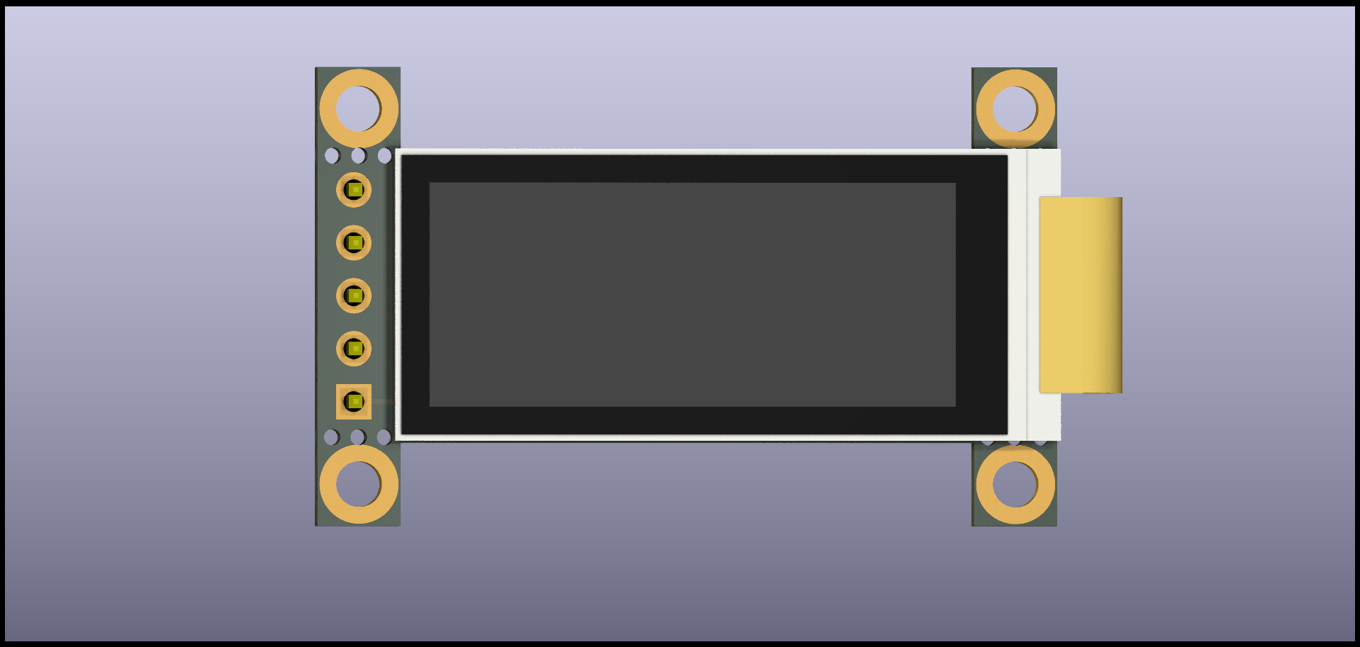
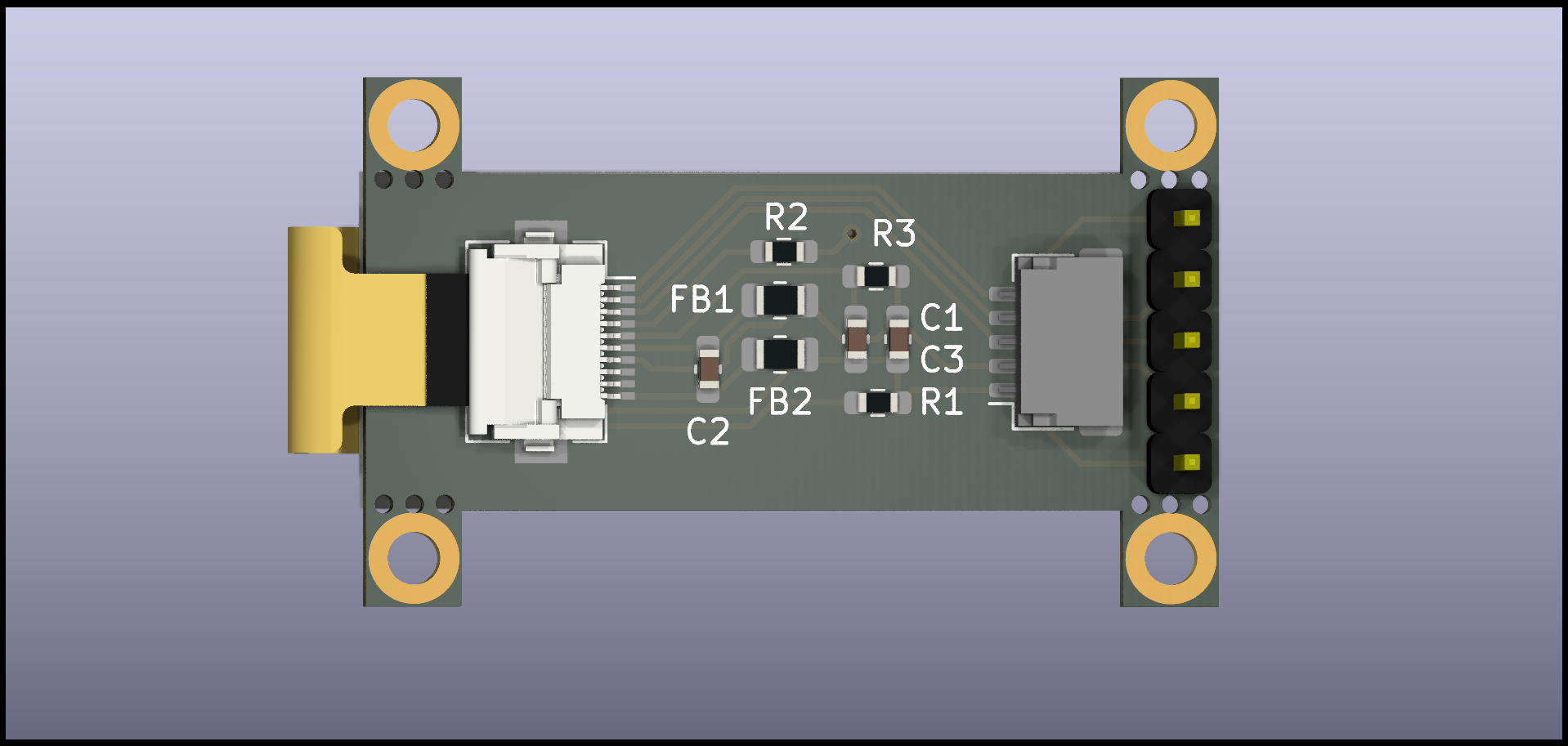

This project is proudly sponsored by NextPCB - Your trusted PCB Prototype & Fabrication Manufacturer. NextPCB provides high-quality PCB manufacturing services with fast turnaround times, making them the perfect partner for bringing electronics projects to life.
This repository contains a few different versions of the breakout board. Production files (Gerber, schematic, STEP) for all versions are available in the Releases section.
This is the original design. It is designed with the pinout of a 128x32 OLED display in mind, making it a potential replacement for common displays used in mechanical keyboards.
To support the growing ecosystem around the nice!view, compatible versions of this breakout are available. These are intended as a DIY alternative if the nice!view is out of stock. They use the same pinout and should work with the same ZMK configurations.
niceview-compat: Pin-compatible with mounting holes.

niceview-compat-no-mount: Pin-compatible without mounting holes for a smaller footprint.

Note: This is a DIY project. For a ready-to-use product, consider purchasing the nice!view instead.
The original version is mostly pin-compatible with standard 128x32 I2C OLED displays used in many split keyboards. To replace an OLED, you may need to connect the CLK pin to a free GPIO on your microcontroller.

The breakout can be used in several ways:
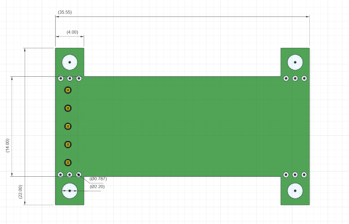
If you need a smaller board, the mounting hole tabs can be carefully broken off.
| Ref | Qty | Value | Footprint | LCSC Part # | Notes |
|---|---|---|---|---|---|
| C1 | 1 | 560pF or 680pF | 0603 | C84721 | Unpolarized Capacitor |
| C2,C3 | 2 | 1uF | 0603 | C15849 | Unpolarized Capacitor |
| FB1,FB2 | 2 | Ferrite Bead | 0805 | C1017 | |
| J2 | 1 | FH12-10S-0.5SH | - | C506791 | FPC Connector |
| J3 | 1 | JST SH 5x1 | - | AliExpress | Optional |
| R1,R2,R3 | 3 | 10kΩ | 0603 | C25804 | Optional |
| Display | 1 | LS011B7DH03 | - | AliExpress |
Notes:
This is a DIY project. The approximate cost for a single breakout board is $15 - $20 (before shipping), assuming you order 5 PCBs from a service like NextPCB and source the displays from AliExpress. Costs can be reduced by sourcing components from cheaper vendors and self-assembly.
For comparison, the pre-built nice!view is sold for around $20.
The breakout has been tested with CircuitPython, Arduino, and ZMK (on an nrfmicro). Example code can be found in the test_code folder.
| Qty | Value | Footprint | References |
|---|---|---|---|
| 4 | MountingHole | MountingHole:MountingHole_2.2mm_M2_DIN965_Pad | H1, H2, H3, H4 |
| 3 | 10k | Resistor_SMD:R_0603_1608Metric_Pad0.98x0.95mm_HandSolder | R1, R2, R3 |
| 2 | Ferrite_Bead_Small | Resistor_SMD:R_0805_2012Metric_Pad1.20x1.40mm_HandSolder | FB1, FB2 |
| 1 | 1uF | Capacitor_SMD:C_0603_1608Metric_Pad1.08x0.95mm_HandSolder | C2 |
| 1 | 1uF | Capacitor_SMD:C_0603_1608Metric_Pad1.08x0.95mm_HandSolder | C3 |
| 1 | 560pF/680pF | Capacitor_SMD:C_0603_1608Metric_Pad1.08x0.95mm_HandSolder | C1 |
| 1 | Conn_01x05 | Connector_PinSocket_2.54mm:PinSocket_1x05_P2.54mm_Vertical | J1 |
| 1 | Conn_01x05_Male | Connector_JST:JST_SH_SM05B-SRSS-TB_1x05-1MP_P1.00mm_Horizontal | J3 |
| 1 | Conn_01x10 | Connector_FFC-FPC:Hirose_FH12-10S-0.5SH_1x10-1MP_P0.50mm_Horizontal | J2 |
The 15 most common of 19 parts.
It measures 35.6 × 22 mm and has 2 copper layers, 1.6 mm thick.
19 parts. The full list of its parts is on this page, with links to each part's symbol and footprint where PCBKit's library has them.
From the karnadii/sharp_memory_display_breakout repository on GitHub, at the commit this page was made from: the board is sharp_memory_display.kicad_pcb and its schematic sharp_memory_display.kicad_sch. PCBKit opens the board in the browser, with nothing to install.
Its repository publishes it under the CERN-OHL-P-2.0 licence: you may reuse it on that licence's terms (keep the author's notice, and for a copyleft licence share your changes alike).

hackclub/OnBoard
💡 Join 1,000 teenagers and make your first PCB with a $100 grant!

polpo/picogus
Emulation of ISA sound cards and CD-ROM on Raspberry Pi Pico (GUS, SB/Adlib, MPU-401, Tandy, CMS, Panasonic CD-ROM) with USB mouse/joystick support


nkitanov/iaq_board
IAQ Board is a DIY (Do-It-Yourself) device for measuring internal air quality


Ardumower/ardumower
Develop an open source robotic lawn mower (HW+SW reference platform)

zmaker/arduino_cookbook
gli sketch del nuovo progetto Arduino Cookbook e dei video di YouTube