2 layers54 × 35 mm
Controller
kamilix2003/Phase-Shifter
Interface for RF phase shifter as part of phased antenna array
67 parts3MIT

 kamilix2003/Phase-Shifter3
Interface for RF phase shifter as part of phased antenna array
Antenna array is an open-source printed circuit board by kamilix2003, from the kamilix2003/Phase-Shifter repository on GitHub, published under the MIT licence. It is a 2-layer board of 214 × 100 mm with 8 parts on 5 nets, routed with 5 tracks and 0 vias.
It belongs with the radio and wireless and interfaces and adapters boards of this library.
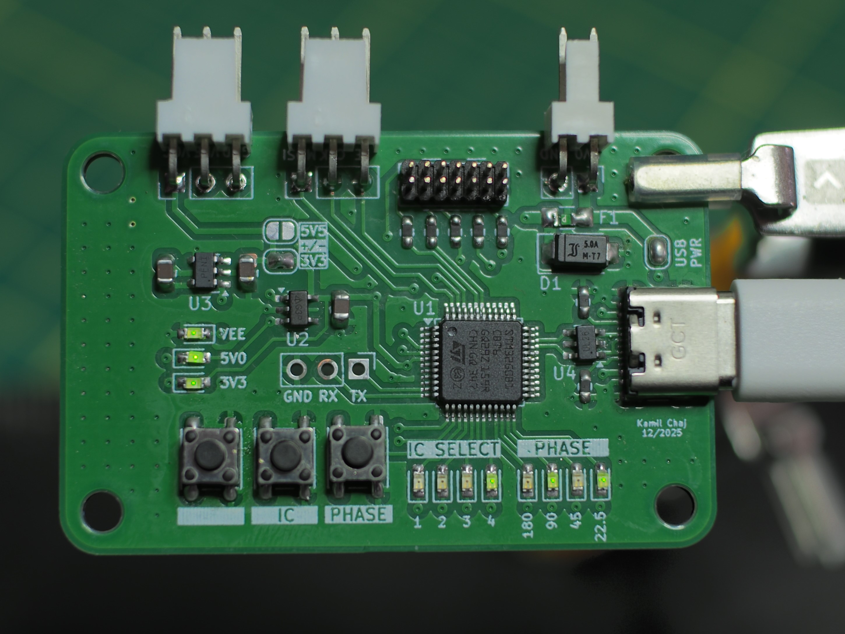
STM32G0B01 based board for controlling daisy-chained digital phase shifter via SPI-like serial interface. User can interface with the board either by buttons and LEDs on the board or via virtual serial port over USB, communication over serial port is realized using simple TLV protocol. The board is providing bipolar supply for the phase shifters.

Available commands:
| Type | Length [bytes] | Value | Description |
|---|---|---|---|
| 0x02 | 1 | command id | Ack |
| 0x10 | 4 | phase shifts (0 - 15) | Set phase |
| 0x11 | 0 | - | Transmit |
| 0x12 | 1 | latch state | Latch state |
After each message microcontroller should send ACK message with payload containing command id of original message
Example routine to set new phase delay:
0x12 0x01 0x00 - make sure that latch is set low in order to accept data via serial interface0x10 0x04 0x04 0x02 0x0f 0x08 - send phase shifts to the controller0x11 0x00 - transmit phase shifts via SPI to the phase shifters0x12 0x01 0x01 - set latch to update phase shift0x12 0x01 0x00 - reset latchThe board is equiped in 3 tactile buttons and two 4-led displays where each display shows according to the silkscreen description either currently selected phase shifter or phase shift set for the selected phase shifter. Buttons have following functions starting from the left most button:
| Qty | Value | Footprint | References |
|---|---|---|---|
| 4 | Antenna | Phase_shifter:patch | AE1, AE2, AE3, AE4 |
| 4 | ~ | Phase_shifter:Conn | J1, J2, J3, J4 |
It measures 214 × 100 mm and has 2 copper layers, 1.6 mm thick.
8 parts. The full list of its parts is on this page, with links to each part's symbol and footprint where PCBKit's library has them.
From the kamilix2003/Phase-Shifter repository on GitHub, at the commit this page was made from: the board is KiCAD/Antenna_array/Antenna_array.kicad_pcb and its schematic KiCAD/Antenna_array/Antenna_array.kicad_sch. PCBKit opens the board in the browser, with nothing to install.
Its repository publishes it under the MIT licence: you may reuse it on that licence's terms (keep the author's notice, and for a copyleft licence share your changes alike).
kamilix2003/Phase-Shifter
Interface for RF phase shifter as part of phased antenna array

kamilix2003/Phase-Shifter
Interface for RF phase shifter as part of phased antenna array

kamilix2003/Phase-Shifter
Interface for RF phase shifter as part of phased antenna array

kamilix2003/Phase-Shifter
Interface for RF phase shifter as part of phased antenna array

kamilix2003/Phase-Shifter
Interface for RF phase shifter as part of phased antenna array


joeycastillo/Sensor-Watch
A board replacement for the classic Casio F-91W wristwatch

rusefi/rusefi
rusefi - GPL internal combustion engine control unit

hoglet67/RGBtoHDMI
Bare-metal Raspberry Pi project that provides pixel-perfect sampling of Retro Computer RGB/YUV video and conversion to HDMI

shanteacontrols/OpenDeck
A platform for building interactive control and sensing devices using MIDI and OSC built with Zephyr RTOS.

hackclub/OnBoard
💡 Join 1,000 teenagers and make your first PCB with a $100 grant!

dangiu/PicoMemcard
Emulating PSX Memory Card (or controller) using a Raspberry Pi Pico

OLIMEX/DIY-LAPTOP
Do It Yourself Open Source Hardware and Software Modular Hacker's Friendly Laptop