

4 layers17 × 22.1 mm

 kajusK/DarkStar6
Small, lightweight and waterproof headlamp with two Cree XP-G2 leds.
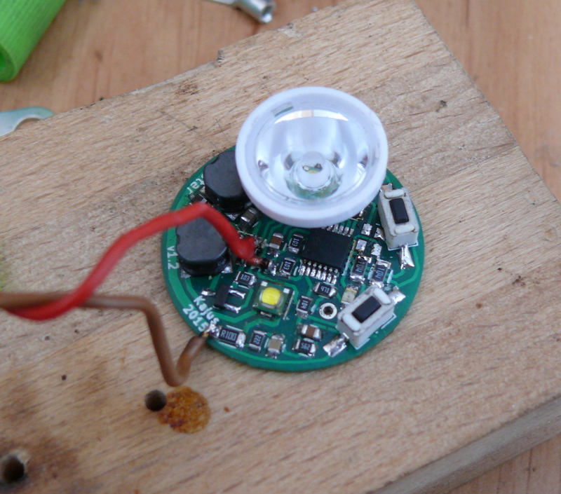
Led driver is an open-source printed circuit board by kajusK, from the kajusK/DarkStar repository on GitHub. It is a 2-layer board of 13.7 × 7.5 mm with 40 parts on 26 nets, routed with 428 tracks and 0 vias.
It is built around the BAT60A and DMP2305U. Its parts include 17 resistors, 6 capacitors, 6 diodes, 2 transistors and 2 connectors. It belongs with the PIC boards of this library.
There's a whole new version with mutch more features and power: https://github.com/kajusK/Darkstar-Mk.II/
Small, lightweight and waterproof LED headlamp with two Cree XP-G2 leds. Can be used in biking, caving, mine exploration, hiking... But always carry a backup light source.
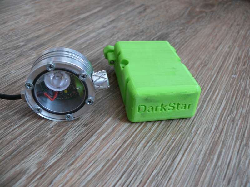
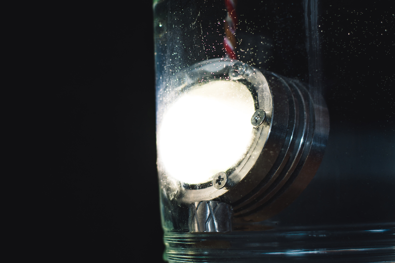
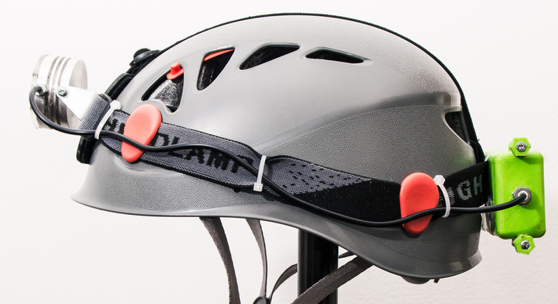
Li-Ion cells can catch fire or explode if not handled properly. The hardware design was NOT extensively tested, the headlamp could die any time, don't rely on it as a single source of light.
The headlamp body can get quite hot if both LEDs are running on full power, there's no thermal protection, you have been warned.
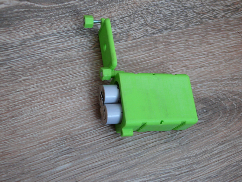
This headlamp is provided under open source license WITHOUT ANY WARRANTY, see LICENSE for more details.
For overview how the hardware works, check microchip application note and source code README.
To reduce manufacturing costs, the heat from CREE LEDs is transferred to aluminium body using several plated vias under the LED itself thus avoiding the need for aluminium PCB or big star heat sink for each LED. For some math background, check the Cree thermal management guide.
Power wires are soldered directly to the PCB. To program the MCU, solder wires to ICSP pins or build some kind of pin-touch interface. Use make in pic directory to compile the sources (assuming you are running Linux), you can use make burn to upload the firmware using pickit2.
The wide beam LED can be used without lenses, the beam is wide enough for my needs, for the narrow beam LED you can buy any compatible lens (it will require some modifications due to limited space on PCB though). I used [17mm 10deg lens] (http://www.aliexpress.com/item/Free-shipping-cree-xp-g-lens-Diameter-17mm-Smooth-surface-with-stand-Condenser-lenses-10-deg/777222733.html)
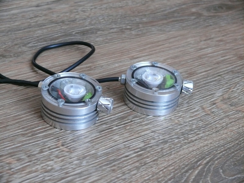
The body is made from a piece of aluminium 6082 T6 using a small lathe. The top cover is made from plexiglass taken from old diving goggles. Waterproofness is ensured by big O-ring between body and glass and two small O-rings on the control knob. The body works also as a heat sink for LEDs, therefore it cannot be made from plastic (e.g. on 3D printer).
The battery box is printed on 3D printer from ABS (I would rather use aluminium, but I don't have access to milling machine).
See Bill of Materials.
| Qty | Value | Footprint | References |
|---|---|---|---|
| 4 | 10k | Resistors_SMD:R_0805 | R2, R10, R11, R14 |
| 3 | 1u | Capacitors_SMD:C_0805 | C2, C4, C8 |
| 2 | 0,1R | Resistors_SMD:R_1206 | R5, R17 |
| 2 | 10k | Resistors_SMD:R_1206 | R13, R15 |
| 2 | 180k | Resistors_SMD:R_0805 | R3, R6 |
| 2 | 1n | Capacitors_SMD:C_0805 | C5, C6 |
| 2 | 22uH | Choke_SMD:Choke_SMD_Wuerth-WE-PD2-Typ-MS | L1, L2 |
| 2 | 2k2 | Resistors_SMD:R_0805 | R8, R18 |
| 2 | 5k6 | Resistors_SMD:R_0805 | R4, R7 |
| 2 | 82R | Resistors_SMD:R_0805 | R1, R12 |
| 2 | BAT60A | Diodes_SMD:SOD-323 | D1, D4 |
| 2 | DMP2305U | Housings_SOT-23_SOT-143_TSOT-6:SOT-23_Handsoldering | Q1, Q2 |
| 1 | 470R | Resistors_SMD:R_0805 | R19 |
| 1 | 470n | Capacitors_SMD:C_0805 | C1 |
| 1 | DOWN | Buttons_Switches_SMD:SW_SPST_FSMSM | SW2 |
| 1 | ICSP | Housings_SOT-23_SOT-143_TSOT-6:SOT-143 | P2 |
| 1 | LED | LEDs:LED-0805 | D7 |
| 1 | LED1 | LEDs:LED-XP-G_CREE | D2 |
| 1 | LED2 | LEDs:LED-XP-G_CREE | D5 |
| 1 | LL103 | Diodes_SMD:Diode-MiniMELF_Standard | D6 |
| 1 | PIC16(L)F616-I/ST | Housings_SSOP:TSSOP-14_4.4x5mm_Pitch0.65mm | U1 |
| 1 | POWER | Connect:GS2 | P1 |
| 1 | UP | Buttons_Switches_SMD:SW_SPST_FSMSM | SW1 |
The 38 most common of 40 parts.
It measures 13.7 × 7.5 mm and has 2 copper layers, 1.6 mm thick.
40 parts, built around the BAT60A and DMP2305U. The full list of its parts is on this page, with links to each part's symbol and footprint where PCBKit's library has them.
From the kajusK/DarkStar repository on GitHub, at the commit this page was made from: the board is pcb/led_driver.kicad_pcb. PCBKit opens the board in the browser, with nothing to install.
Its repository states no licence, so its author keeps all rights: ask kajusK before reusing the design.


M17-Project/Module_17
M17 modem board for 9600-baud capable radios


crgarcia12/electronics-homeassistant-lightscontroll
A smart lighting controller PCB that integrates seamlessly with ESPHome and Home Assistant while maintaining full compatibility with traditional mechanical switches.
