

2 layers84.3 × 58.4 mm
EnocderDriver
NikodemBartnik/Small-Projects
All of smaller projects (Arduino, PCBs, electronics, code)
35 parts55

ARCHIVED FINAL — Altera MAX 7000S (5V) / MAX 7000AE (3.3V) CPLD board. Calculator-full-5v (EPM7064S) + Calculator-full-3v3 (EPM7064AE), board tests, KiCad, ELEC 211. White board photo = 5V 7000S.
Cpld is an open-source printed circuit board by K9DTV, from the K9DTV/cpld-development-system repository on GitHub, published under the MIT licence. It is a 2-layer board of 70.4 × 80.1 mm with 24 parts on 36 nets, routed with 864 tracks and 82 vias.
It is built around the LM1117-5.0 and LM1117-3.3. Its parts include 8 capacitors, 7 ICs, 4 resistors, 2 connectors and 1 switch. It belongs with the fPGA and programmable logic boards and the FPGA and CPLD boards of this library.

Archived — final / last release. This project is complete and frozen. Issues and PRs are not expected; the tree is the historical record.







A hand-designed Altera MAX 7000AE/S CPLD development board and the digital labs built on it — from Lake Washington Institute of Technology Electronics 211 (2017–2018), by James Burney (K9DTV).
This repository packs the PCB design, fabrication outputs, board photos, project write-ups, and a Quartus calculator experiment that targeted the board.
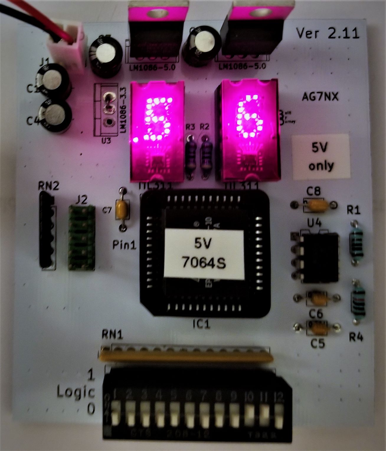
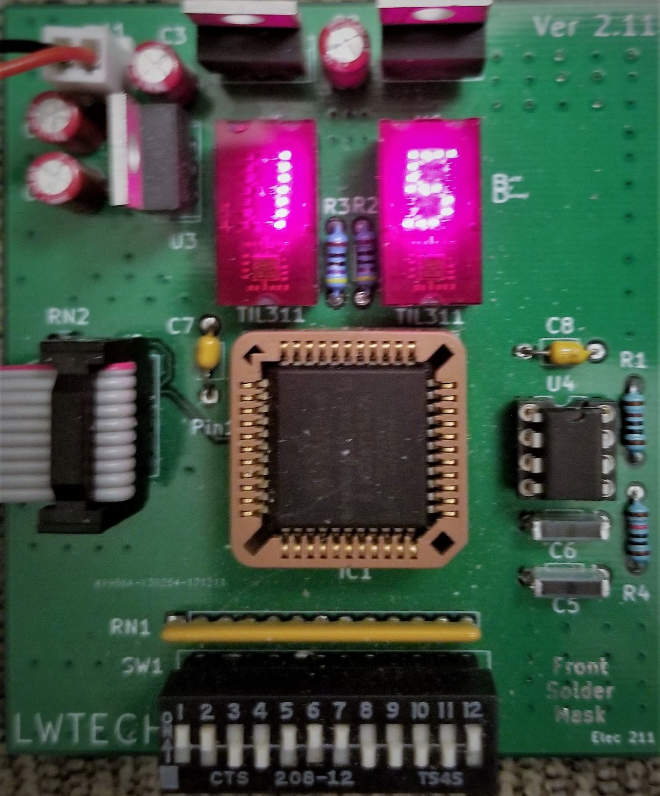
Left (white / Ver2): board pictured with the MAX 7000S 5 V CPLD setup. Right (green): Ver1-style build.
The goal was a durable printed CPLD trainer for the same class work that started on a hand-wired prototype: DIP switches in, dual hexadecimal TIL311-style displays out, on-board clock, and a standard JTAG/ByteBlaster programming header.
Two PCB revisions shipped:
| Version | How to spot it | Notes |
|---|---|---|
| Ver1 | No silkscreen | Used for most lab examples in the docs |
| Ver2 | Has silkscreen | Three display-control pins remapped (see pin table below) |
Power: about 6.5 V–12 V input (prefer the low end; regulators get hot). Current-limit around 160 mA when using a bench supply. Drive each display decimal point with an open-drain buffer so the DP turns fully off.
Same PLCC-44 socket and the same lab/pin idea. The difference is supply voltage / family:
| Family | Example parts | Core / I/O | Notes |
|---|---|---|---|
| MAX 7000S | EPM7032, EPM7064S | 5 V | White board photo; use Calculator-full-5v |
| MAX 7000AE | EPM7032AE, EPM7064AE | 3.3 V | Use Calculator-full-3v3 |
Same calculator logic / pinout in both folders — pick the build that matches the CPLD voltage on the board. Do not mix a 5 V part with a 3.3 V rail (or the reverse) without checking VCCIO/VCCINT wiring.
Supported CPLDs (PLCC-44):
calulator/Calculator-full-5v/)calulator/Calculator-full-3v3/).
├── README.md
├── cpld-white.jpg / cpld-green.jpg # Assembled boards
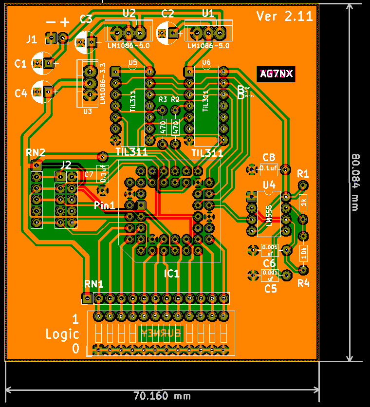
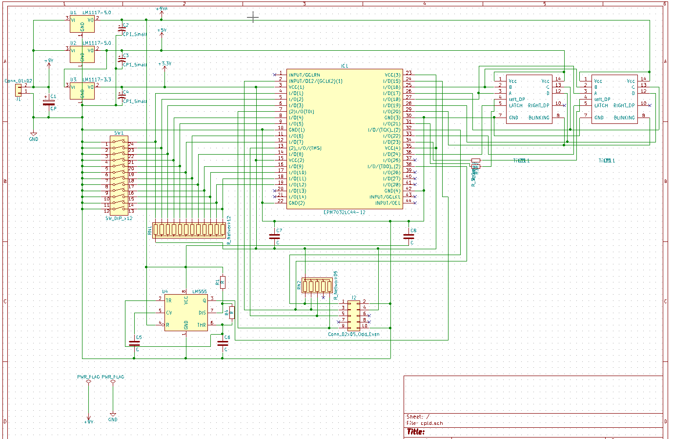
├── cpld-pcb.png / cpld-sch.png # Layout / schematic views
├── PCB-files/
│ ├── cpld/ # KiCad schematic + PCB (legacy KiCad 4 era)
│ └── CLPD-grb/ # Gerbers + drill for fab
├── calulator/ # Quartus II projects (folder spelling preserved)
│ ├── Calculator-full-5v/ # Full calculator — EPM7064S / 5 V
│ ├── Calculator-full-3v3/ # Full calculator — EPM7064AE / 3.3 V
│ ├── board test/ # Board bring-up
│ ├── board-test-2/ # Switch / display exercise (32 MC)
│ └── boardtest3/ # Follow-on board test (uses board-test-2 BDFs)
├── project docs/ # Word write-ups + markdown/ previews for GitHub
└── homework/ # Class notes (ELEC 211 Ch. 4)Folder and filename spellings (calulator, CLPD-grb, spaces in project docs) match the original archive on purpose.
DIP switches are active-low (closed = logic 0). Most designs invert them in the CPLD so “switch ON” reads as a 1 in the logic.
| Function | Ver1 CPLD pin | Ver2 CPLD pin |
|---|---|---|
| DIP SW 1–12 | 4, 5, 6, 8, 9, 12, 11, 14, 16, 17, 19, 18 | same |
| Clock (~66.6 kHz from 555) | 24 | 24 |
| Display A / B / C / D | 27 / 25 / 26 / 28 | same |
| Display Blank | 29 | 29 |
| Right Latch | 31 | 33 |
| Left Latch | 33 | 36 |
| Right DP | 34 | 34 |
| Left DP | 36 | 31 |
Programming-header pins follow the usual Altera JTAG layout (not duplicated in the table).
| Ref | Part | Notes |
|---|---|---|
| IC1 | EPM7032 / EPM7064S (5 V) or EPM7064AE (3.3 V), PLCC-44 | 64 MC for full calculator |
| U1–U2 | LM1117-5.0 | 5 V rails |
| U3 | LM1117-3.3 | CPLD I/O / core as wired |
| U4 | LM555 | ~66.6 kHz board clock |
| U5–U6 | TIL311 (or DIS1417) | Hex displays (hard to source; eBay) |
| SW1 | 12-position DIP slide | Active-low inputs |
| RN1 / RN2 | 10 kΩ SIP arrays | Pull-ups |
| J2 | 2×5 header | Programming |
Full Digi-Key / Mouser part numbers are in project docs/pcb document and cpld project.docx.
Documented in project docs/:
Calculator-full-5v/ (EPM7064S, 5 V) and Calculator-full-3v3/ (EPM7064AE, 3.3 V).two digit counter cpld project.docx).211 build board.docx).calulator/)Intel/Altera Quartus II block-diagram labs. Folder name spelling calulator is preserved. The calculator top entity is named Calculator.
| Folder | Device | I/O standard | Fit | Use when |
|---|---|---|---|---|
Calculator-full-5v/ | EPM7064SLC44-10 (MAX7000S) | TTL (5 V) | 60 / 64 MC | 5 V CPLD (white board photo setup) |
Calculator-full-3v3/ | EPM7064AELC44-10 (MAX7000AE) | 3.3-V LVTTL | 60 / 64 MC | 3.3 V AE CPLD |
Each folder has its own Calculator.qpf, BDFs/BSFs, Calculator.pof, and reports. Ver2 display pins (latch_R=33, latch_L=36, Left_DP=31). Open the folder that matches the chip on the board.
| Folder | Role |
|---|---|
board test/ | Bring-up (boardtest.qpf, .pof included) |
board-test-2/ | Switch/display lab (board-test-2.qpf, EPM7032AE, .pof included) |
boardtest3/ | Later board test (test3.qpf; BDFs referenced from ../board-test-2/) |
Suggested tools: Quartus II 13.0 SP1 (or 17.1 Lite) with a USB-Blaster.
PCB-files/)PCB-files/cpld/ — schematic (.sch), board (.kicad_pcb), netlist, project (KiCad 4-style .pro).PCB-files/CLPD-grb/ — Gerber layers (F/B Cu, mask, silk, edge cuts) and cpld.drl.Open with a modern KiCad via the legacy importer, or send the Gerbers straight to a fab.
project docs/)Original Word write-ups stay in the folder (provenance). GitHub-readable Markdown previews (text extracted from those .docx files) live under project docs/markdown/:
| Word (original) | Markdown preview | Contents |
|---|---|---|
211 build board.docx | 211-build-board.md | Hand-wired prototype + Ch. 7 calculator path |
pcb document and cpld project.docx | pcb-document-and-cpld-project.md | Ver1/Ver2 PCB, pin map, BOM, calculator labs |
two digit counter cpld project.docx | two-digit-counter-cpld-project.md | Counter lab on the PCB |
211 PROJECT.docx | 211-project.md | Course project write-up |
211 final.docx | 211-final.md | Final write-up |
Course context: Lake Washington Institute of Technology, Electronics 211, instructor Professor Peter Welty.
MIT -- see LICENSE. Personal educational hardware and reports by James Burney (K9DTV). Course homework notes in homework/ are included as archived class material. Altera/Intel tool output remains under their respective license terms.
Site / project page: k9dtv.com/project-cpld.html · GitHub: K9DTV/cpld-development-system
Archived from the original CPLD development-system materials (2017–2018) and published as a public K9DTV project.
| Qty | Value | Footprint | References |
|---|---|---|---|
| 4 | C | Capacitors_ThroughHole:C_Axial_L3.8mm_D2.6mm_P7.50mm_Horizontal | C5, C6, C7, C8 |
| 3 | CP1_Small | Capacitors_ThroughHole:CP_Radial_D5.0mm_P2.50mm | C2, C3, C4 |
| 2 | LM1117-5.0 | Power_Integrations:TO-220 | U1, U2 |
| 2 | R | Resistors_ThroughHole:R_Axial_DIN0204_L3.6mm_D1.6mm_P7.62mm_Horizontal | R1, R4 |
| 2 | R_Small | Resistors_ThroughHole:R_Axial_DIN0204_L3.6mm_D1.6mm_P7.62mm_Horizontal | R2, R3 |
| 2 | Til311 | Housings_DIP:DIP-14_W7.62mm | U5, U6 |
| 1 | CP | Capacitors_ThroughHole:CP_Radial_D5.0mm_P2.50mm | C1 |
| 1 | Conn_01x02 | Pin_Headers:Pin_Header_Straight_1x02_Pitch2.54mm | J1 |
| 1 | Conn_02x05_Odd_Even | Pin_Headers:Pin_Header_Straight_2x05_Pitch2.54mm | J2 |
| 1 | EPM7032LC44-12 | Sockets:PLCC44 | IC1 |
| 1 | LM1117-3.3 | Power_Integrations:TO-220 | U3 |
| 1 | LM555 | Housings_DIP:DIP-8_W7.62mm | U4 |
| 1 | R_Network05 | Socket_Strips:Socket_Strip_Straight_1x06_Pitch2.54mm | RN2 |
| 1 | R_Network12 | Socket_Strips:Socket_Strip_Straight_1x13_Pitch2.54mm | RN1 |
| 1 | SW_DIP_x12 | Buttons_Switches_ThroughHole:SW_DIP_x12_W7.62mm_Slide | SW1 |
It measures 70.4 × 80.1 mm and has 2 copper layers, 1.6 mm thick.
24 parts, built around the LM1117-5.0 and LM1117-3.3. The full list of its parts is on this page, with links to each part's symbol and footprint where PCBKit's library has them.
From the K9DTV/cpld-development-system repository on GitHub, at the commit this page was made from: the board is PCB-files/cpld/cpld.kicad_pcb. PCBKit opens the board in the browser, with nothing to install.
Its repository publishes it under the MIT licence: you may reuse it on that licence's terms (keep the author's notice, and for a copyleft licence share your changes alike).
NikodemBartnik/Small-Projects
All of smaller projects (Arduino, PCBs, electronics, code)

barisdinc/N3B_SDR_Transceiver_HW
V/U/SHF and QO-100 SDR Transceiver Project

KarlVaello/VehicleControlSystem
Vehicle Control System. Using C++ Qt and C. Hardware and Software

dchwebb/MidiMonger
Eurorack MIDI interface supporting USB and serial MIDI. Based on ARM STM32F446 MCU.


DhruvaG2000/RP2040_Dev_Board
Kicad PCB design for a RP2040 Development Board Designed to make the RP2040 more beginner friendly