2 layers90 × 60 mm
Nexa
KarlVaello/Nexa-Board
Nexa is a Open Source Hardware board based on STM32f103 with a full duplex rs-485 interface
74 parts2GPL-3.0

 KarlVaello/VehicleControlSystem14
Vehicle Control System. Using C++ Qt and C. Hardware and Software
BaseModule is an open-source printed circuit board by KarlVaello, from the KarlVaello/VehicleControlSystem repository on GitHub, published under the GPL-3.0 licence. It is a 2-layer board of 85 × 60 mm with 67 parts on 63 nets, routed with 530 tracks and 45 vias.
It is built around the STM32F103C8T6, MAX485ED and LM1117-3.3, with the LM1117-5.0 among its other parts. Its parts include 22 resistors, 18 connectors, 11 capacitors, 5 ICs and 4 diodes. It belongs with the STM32 boards of this library.


In modern vehicles almost 80% of the vehicle is controlled electronically. That's just VCS, a control system. Focused on electric vehicles but can be easily modified for other types. VCS consists of several units and modules, all connected by an area network bus, based on rs-485 and my own data protocol, allowing modularization. In this project you will find both the hardware and the software of each unit or module.
 Electronic control units / modules
UNITS:
MODULES:
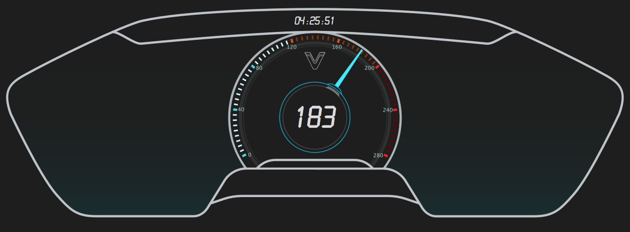
BASE MODULE

See the WIKI for full documentation, examples, operational details and other information.
| Qty | Value | Footprint | References |
|---|---|---|---|
| 8 | 10k | Resistors_SMD:R_0603_HandSoldering | R7, R8, R9, R10, R11, R12, R13, R14 |
| 5 | Conn_01x02_Male | Pin_Headers:Pin_Header_Straight_1x02_Pitch2.54mm | J2, J9, J10, J12, J13 |
| 4 | 100nF | Capacitors_SMD:C_0603_HandSoldering | C1, C3, C4, C5 |
| 4 | 20K | Resistors_SMD:R_0603_HandSoldering | R15, R16, R17, R18 |
| 4 | 20pF | Capacitors_SMD:C_0603_HandSoldering | C6, C7, C8, C9 |
| 4 | 510R | Resistors_SMD:R_0603_HandSoldering | R3, R4, R21, R22 |
| 4 | LED | LEDs:LED_0805_HandSoldering | D1, D2, D3, D4 |
| 3 | Conn_01x01 | Pin_Headers:Pin_Header_Straight_1x01_Pitch2.54mm | J14, J15, J16 |
| 2 | 100K | Resistors_SMD:R_0603_HandSoldering | R5, R6 |
| 2 | 100nF | Capacitors_SMD:C_0805_HandSoldering | C10, C11 |
| 2 | 10uF | Capacitors_Tantalum_SMD:CP_Tantalum_Case-B_EIA-3528-21_Hand | CP1, CP3 |
| 2 | 120R | Resistors_SMD:R_0603_HandSoldering | R19, R20 |
| 2 | 22uF | Capacitors_Tantalum_SMD:CP_Tantalum_Case-B_EIA-3528-21_Hand | CP2, CP4 |
| 2 | Conn_02x02_Top_Bottom | Pin_Headers:Pin_Header_Straight_2x02_Pitch2.54mm | J7, J8 |
| 2 | MAX485E | Housings_SOIC:SOIC-8_3.9x4.9mm_Pitch1.27mm | U4, U5 |
| 1 | 1.0uF | Capacitors_SMD:C_0603_HandSoldering | C2 |
| 1 | 10K | Resistors_SMD:R_0603_HandSoldering | R1 |
| 1 | 1M | Resistors_SMD:R_0603_HandSoldering | R2 |
| 1 | 32.768 KHz | Crystals:Crystal_SMD_SeikoEpson_MC306-4pin_8.0x3.2mm_HandSoldering | Y2 |
| 1 | 8 MHz | Crystals:Crystal_HC49-4H_Vertical | Y1 |
| 1 | Conn_01x02_Top_Bottom | Pin_Headers:Pin_Header_Straight_1x02_Pitch2.54mm | J17 |
| 1 | Conn_01x04 | Pin_Headers:Pin_Header_Straight_1x04_Pitch2.54mm | J1 |
| 1 | Conn_01x04 | Connectors_Molex:Molex_MiniFit-JR-5569-04A2_2x02x4.20mm_Angled | J3 |
| 1 | Conn_01x15_Male | Socket_Strips:Socket_Strip_Straight_1x21_Pitch2.54mm | J5 |
| 1 | Conn_02x02_Top_Bottom | Socket_Strips:Socket_Strip_Straight_1x04_Pitch2.54mm | J18 |
| 1 | Conn_02x03_Odd_Even | Pin_Headers:Pin_Header_Straight_2x03_Pitch2.54mm | J4 |
| 1 | DB9_Female | SparkFun-Connectors:DB9 | J11 |
| 1 | LM1117-3.3 | TO_SOT_Packages_SMD:SOT-223 | U3 |
| 1 | LM1117-5.0 | TO_SOT_Packages_SMD:SOT-223 | U2 |
| 1 | STM32F103C8 | Housings_QFP:LQFP-48_7x7mm_Pitch0.5mm | U1 |
| 1 | SW_Push | Buttons_Switches_THT:SW_PUSH_6mm_h8.5mm | SW1 |
| 1 | proto_grid_15x21 | CarlosVaello:grid | J6 |
It measures 85 × 60 mm and has 2 copper layers, 1.6 mm thick.
67 parts, built around the STM32F103C8T6, MAX485ED, LM1117-3.3 and LM1117-5.0. The full list of its parts is on this page, with links to each part's symbol and footprint where PCBKit's library has them.
From the KarlVaello/VehicleControlSystem repository on GitHub, at the commit this page was made from: the board is modules/BaseModule/BaseModule.kicad_pcb. PCBKit opens the board in the browser, with nothing to install.
Its repository publishes it under the GPL-3.0 licence: you may reuse it on that licence's terms (keep the author's notice, and for a copyleft licence share your changes alike).
KarlVaello/Nexa-Board
Nexa is a Open Source Hardware board based on STM32f103 with a full duplex rs-485 interface

NikodemBartnik/Small-Projects
All of smaller projects (Arduino, PCBs, electronics, code)

barisdinc/N3B_SDR_Transceiver_HW
V/U/SHF and QO-100 SDR Transceiver Project

dchwebb/MidiMonger
Eurorack MIDI interface supporting USB and serial MIDI. Based on ARM STM32F446 MCU.


DhruvaG2000/RP2040_Dev_Board
Kicad PCB design for a RP2040 Development Board Designed to make the RP2040 more beginner friendly