
2 layers76.2 × 61.9 mm
Digits pcb
justinlindh/digits
Encrypted retro phone network — private VoIP over vintage desk phones
71 parts4AGPL-3.0

 justinlindh/digits4
Encrypted retro phone network — private VoIP over vintage desk phones
Digits pcb is an open-source printed circuit board by justinlindh, from the justinlindh/digits repository on GitHub, published under the AGPL-3.0 licence. It is a 2-layer board of 61.9 × 76.2 mm with 77 parts on 104 nets, routed with 909 tracks and 131 vias.
It is built around the RP2040, DRV8871DDARQ1 and TLV320AIC3104IRHBR, with the W25Q16JVSSIQ, XL6019E1 and AMS1117-3.3 among its other parts. Its parts include 43 capacitors, 10 resistors, 7 ICs, 4 diodes and 2 switches. It belongs with the retro computing and games boards and the RP2040 boards of this library.


Private encrypted phone network built from gutted vintage desk phones.


Each phone is a gutted vintage desk phone with two processors inside: an RP2040 handling real-time phone hardware (keypad scanning, hook switch, bell ringer, DTMF tones) and a Raspberry Pi Zero 2 W running a Go daemon for VoIP, end-to-end encrypted media (DTLS-SRTP), and call signaling. A Go server handles call routing, device pairing, and household management. There's a free public instance at app.digits.family, or you can run your own.
| Component | Role |
|---|---|
| RP2040 (firmware, C) | Real-time phone I/O: keypad matrix, hook switch, bell driver, DTMF/tone generation, status LED. Communicates with the Pi over UART. V0/V1 use a Pico H module; V2/V3 have the RP2040 onboard. |
| Pi Zero 2 W (digitsd, Go) | VoIP daemon: WebRTC media, Opus codec, DTLS-SRTP, signaling client, call state machine, Wi-Fi setup, OTA updates. |
| Audio codec | Mic input and earpiece output. Codec Zero HAT (DA7212) on V0/V1, onboard TLV320AIC3104 on V2/V3. |
| Signaling server (Go) | WebSocket relay for SDP/ICE exchange, PostgreSQL persistence, device pairing, household management, web dashboard. |
Calls are peer-to-peer WebRTC sessions between two phones (or three, for party-line calls). The server brokers the signaling handshake but never handles media.
See Architecture deep-dive for the full call path, data model, and NAT traversal.
Four hardware iterations, each a different build strategy:
| Rev | Construction | Audio | Ringer | Status |
|---|---|---|---|---|
| V0 | Perfboard, off-the-shelf modules | Codec Zero HAT (DA7212) | L298N + step-up transformer | Done, documented end-to-end |
| V1 | Hand-assembled PCB, Pico H module | Codec Zero HAT (DA7212) | L298N + step-up transformer | Fabricated, has errata |
| V2 | Contract-assembled (JLCPCB), onboard RP2040 | Onboard TLV320AIC3104 | Onboard DRV8871 | Deployed, ~10 units in use |
| V3 | Contract-assembled (JLCPCB), onboard RP2040 | Onboard TLV320AIC3104 | Onboard DRV8871 + XL6019 boost | In progress, see changes |
V1 is a bench-build target: single-sided, mostly through-hole, hand-solderable. External modules handle audio (Codec Zero HAT) and bell ringing (L298N H-bridge plus a step-up transformer).
V2 is a fab-service target: onboard RP2040, audio codec (TLV320AIC3104, 32-pin QFN), and ringer driver (DRV8871). Arrives pre-assembled from JLCPCB. Not practical to hand-solder.
V3 is a major spin of V2: +5 V input (the 12 V buck stage is gone), an on-board XL6019 boost converter making ~37 V to ring the bell in place of the external step-up transformer, a single DPDT cradle switch for hook sense and series mic-kill, an SW2 BOOTSEL button, power indicator LEDs, components flipped to face up, and J8/LED pinouts matched to the stock donor-phone cables. Like V2, it arrives pre-assembled from JLCPCB.
Schematics, PCB layouts, Gerbers, and BOMs are in hardware/pcb/. All designed in KiCad. The firmware abstracts board differences at runtime, so the same binary runs on V1, V2, and V3.
firmware/       RP2040 firmware (C, CMake, Pico SDK)
pi/digitsd/     Pi-side VoIP daemon (Go, cross-compiled to arm64)
pi/image/       Raspberry Pi OS image builder
server/         Signaling server + web dashboard (Go, htmx, Tailwind)
hardware/pcb/   KiCad schematics, PCB layouts, Gerbers, BOMs
charts/digits/  Helm chart for Kubernetes deployment
tools/          Build scripts for firmware, Pi binaries, and OS images
docs/           Architecture notes, build guides, self-hosting
scripts/ Firmware build and flash helperscd server
make build # builds bin/signald
make run # build + run (defaults to :8443)
make test # go test ./...Requires Go 1.26+ and PostgreSQL. The server reads DATABASE_URL and runs migrations on startup.
./scripts/build.sh     # auto-detects PICO_SDK_PATH
./scripts/flash.sh # hold BOOTSEL, plug in USB, then runcd pi/digitsd
make build # cross-compiles to linux/arm64 via Docker
make build-local # native build (requires cross-compile libs)
make testThe server is a single Go binary (signald) backed by Postgres. For calls across different networks, you also need a TURN relay (coturn). Docker Compose is the straightforward way to run both: clone the repo, fill in an .env file, docker compose up -d. The self-hosting guide covers the full setup including TURN, TLS, SMTP for magic-link auth, phone pairing, backups, and troubleshooting.
There is also a Helm chart if you happen to have a Kubernetes cluster. There is no good reason for a family phone network to run on k8s, but I over-engineered almost everything in this project and it would have felt wrong to stop at the deployment layer. The chart supports CNPG Postgres, Redis Sentinel for multi-replica signaling, OpenTelemetry tracing, Pyroscope profiling, and Prometheus metrics. It is what runs in production. Completely unnecessary, but it works and it is there if you want it.
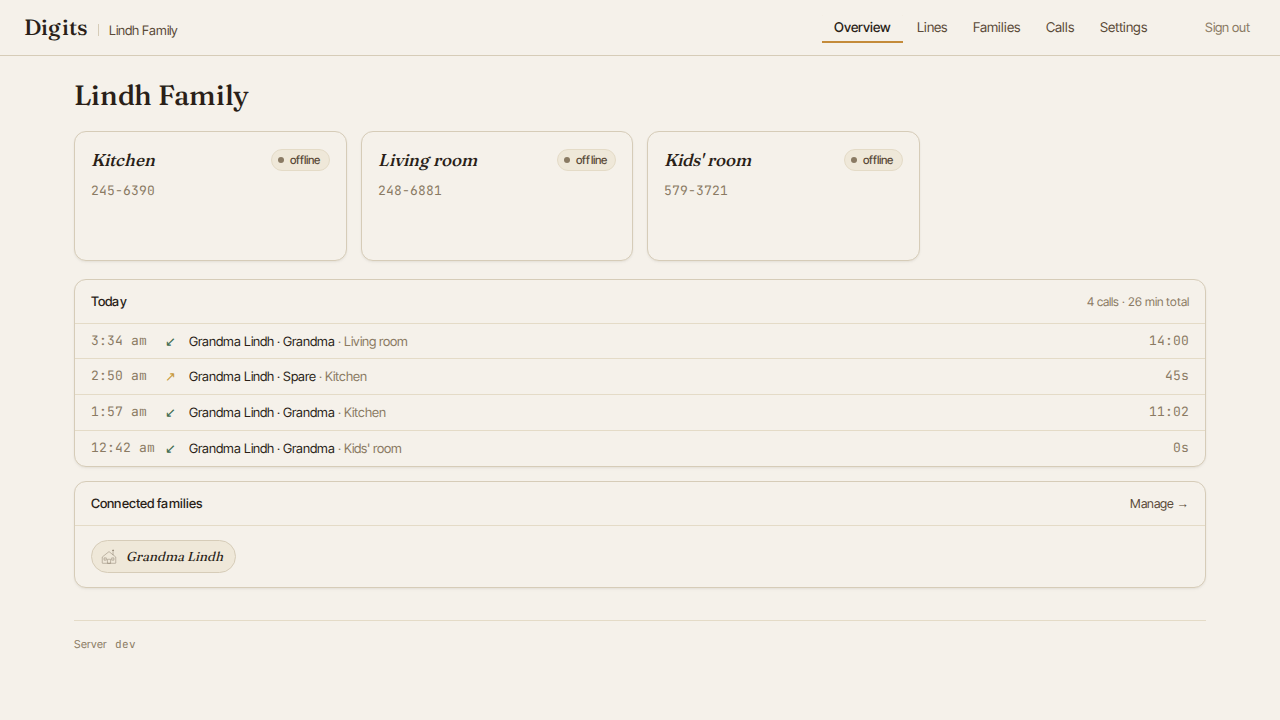
The server includes a web dashboard for pairing phones, organizing households, viewing call history, and configuring per-line settings.
Hidden codes entered on the keypad while the handset is off-hook.
| Code | Action | Details |
|---|---|---|
*#*0 -- *#*9 | Volume | Sets earpiece volume (0 = quiet, 9 = max). Persists across reboots. |
*#8378# | Audio test | Records 5 s from mic, plays it back through earpiece. (*#TEST# on keypad.) |
*#*# | Shutdown | Graceful power-off. Safe to unplug after LED goes dark. |
*##* | Reboot | Immediate reboot. |
*#0* | Force re-pair | Clears device token, reboots into pairing mode. |
*#73887# | Wi-Fi setup | Reboots into AP mode for Wi-Fi reconfiguration. (*#SETUP# on keypad.) |
*#873283# | Update check | Checks for OTA firmware and daemon updates. (*#UPDATE# on keypad.) |
*#00000# | Factory reset | Wipes config, Wi-Fi, contacts. Fresh AP + pairing mode. |
| Code | Action | Details |
|---|---|---|
*69 | Call return | Announces who last called you. Press 1 to call them back. If the line is busy, the system retries for 30 minutes and rings you with a distinctive pattern when the line is free. |
*89 | Cancel call return | Cancels any pending *69 busy-retry. Voice confirmation plays. |
These are dialed from dial tone (not prefixed with *#), matching the original 1990s POTS behavior.
| Code | Action | Details |
|---|---|---|
*96 | Audition greeting | Plays your current outgoing greeting through the earpiece, so you can hear what callers hear. |
*97 | Record greeting | Records a custom outgoing greeting after the tone. |
*98 | Listen to messages | Plays your messages oldest first, then any saved (already heard) messages. During playback: 7 deletes, 9 saves, # skips, * replays. |
*99 | Delete greeting | Removes your custom greeting and restores the default. |
When a call rings unanswered past the configured timeout, the phone answers it, plays your greeting, and records the caller's message. The handset microphone is muted while recording, so a caller never hears your room. See the voicemail guide for using and configuring it, or Voicemail for the engineering reference: FSM, on-disk storage format, signaling, and configuration.
Classic 90s residential three-way calling. During an active call, press and briefly release the hook switch (a "flash", 100-600 ms on-hook) to get a second dial tone. Dial a third number, talk to them privately, then flash again to merge all three into a single call.
| Gesture | What happens |
|---|---|
| Flash during an active call | Held party drops to silent hold; you hear a second dial tone |
| Dial a number | Ringback; third party's phone rings |
| Flash again after they answer | All three merged into the conference |
| Flash before they answer | Drops the add attempt; returns to the held party |
| Hang up (host) | Collapses the conference for everyone |
| Hang up (non-host) | Remaining pair keeps talking as a normal 2-party call |
Hard-capped at three parties, matching residential TWC on 5ESS / DMS-100 switches. Audio stays end-to-end encrypted on three independent DTLS-SRTP legs; the server never sees media, and mixing happens locally on each phone.
See Party Line for the state machine, media topology, signalling protocol, and failure-mode coverage.
Hidden sequences that play audio clips through the earpiece. Each keypress must be within ~1.5 s of the last.
| Sequence | What plays |
|---|---|
5-5-4-2 | Towelie: "That's it! That's the melody to Funky Town!" |
0-0-0-0 | Rick Astley: "Never gonna give you up..." |
8-6-7-5-3-0-9 | Tommy Tutone: "Jenny I got your number... 867-5309!" (intercepts the dial) |
Calls use WebRTC with DTLS-SRTP. Voice data is encrypted end-to-end between the two devices on the call. The signaling server facilitates connection setup but never has access to the audio stream. Even if the server were compromised, there would be no voice data to extract.
A dedicated hardware kill switch (separate from the hook switch) physically disconnects the microphone circuit when the handset is on the cradle. This is an electrical disconnect, not a software mute.
What the server stores: user accounts (email, name), household membership, phone line assignments, device pairing tokens, session data, call metadata (caller, callee, timestamps, duration), and connection quality telemetry (packet loss, jitter, bandwidth).
What the server does not store: voice audio, call recordings, transcripts, or location data. There is no mechanism in the server to capture call audio.
The server is designed to be self-hosted. If you do not want to use the public instance at app.digits.family, you can run the same code on your own infrastructure. See Self-hosting.
This is a personal project, not a company. Contributions to both the software and the hardware are welcome.
On the software side, the server is vanilla Go with htmx and Tailwind, the Pi daemon is Go with WebRTC, and the firmware is C on the Pico SDK. Standard open source workflow: fork, branch, PR.
On the hardware side, I am not an electrical engineer. I learned KiCad, read datasheets, and iterated until the board worked. The result is a functional PCB with minimal errata, which I'm genuinely proud of, but there is a lot of room for someone with real PCB design experience to improve the layout, power integrity, signal routing, and DFM. If you have those skills and this project interests you, I would particularly welcome that kind of help. The schematics and board files are all KiCad and licensed CC BY-SA 4.0.
Code (firmware, server, tooling): AGPL-3.0
Hardware (schematics, PCB layout, BOM): CC BY-SA 4.0
| Qty | Value | Footprint | References |
|---|---|---|---|
| 24 | 100nF | Capacitor_SMD:C_0402_1005Metric | C12, C13, C14, C15, C16, C28, C29, C30, C32, C33, C34, C35, C36, C38, C40, C41 +8 |
| 4 | 1uF | Capacitor_SMD:C_0402_1005Metric | C10, C31, C39, C44 |
| 3 | MountingHole | MountingHole:MountingHole_3.2mm_M3 | MH1, MH2, MH3 |
| 2 | 0.47uF | Capacitor_SMD:C_0402_1005Metric | C46, C47 |
| 2 | 100nF | Capacitor_SMD:C_0805_2012Metric | C3, C4 |
| 2 | 10k | Resistor_SMD:R_0402_1005Metric | R5, R11 |
| 2 | 10uF | Capacitor_SMD:C_0402_1005Metric | C37, C45 |
| 2 | 10uF | Capacitor_SMD:C_0603_1608Metric | C9, C11 |
| 2 | 15pF | Capacitor_SMD:C_0402_1005Metric | C5, C6 |
| 1 | 1.5A | Fuse:Fuse_1210_3225Metric | F1 |
| 1 | 100uF | cap-out-lcsc:CAP-SMD_BD10.0-L10.3-W10.3-FD | C100 |
| 1 | 10uF | Capacitor_SMD:CP_Elec_5x5.3 | C55 |
| 1 | 120 | Resistor_SMD:R_0402_1005Metric | R13 |
| 1 | 1k | Resistor_SMD:R_0402_1005Metric | R9 |
| 1 | 1nF | Capacitor_SMD:C_0402_1005Metric | C53 |
| 1 | 1uF | Capacitor_SMD:C_0805_2012Metric | C101 |
| 1 | 2.2k | Resistor_SMD:R_0402_1005Metric | R10 |
| 1 | 220 | Resistor_SMD:R_0805_2012Metric | R1 |
| 1 | 2k | Resistor_SMD:R_0402_1005Metric | R21 |
| 1 | 300 | Resistor_SMD:R_0402_1005Metric | R12 |
| 1 | 33k | Resistor_SMD:R_0402_1005Metric | R2 |
| 1 | 470uF | Capacitor_SMD:CP_Elec_10x10.5 | C1 |
| 1 | 47uH | inductor-lcsc:IND-SMD_L12.3-W12.3 | L10 |
| 1 | 57.6k | Resistor_SMD:R_0402_1005Metric | R20 |
| 1 | ABM8-272-T3 | Crystal:Crystal_SMD_3225-4Pin_3.2x2.5mm | Y1 |
| 1 | AMS1117-3.3 | Package_TO_SOT_SMD:SOT-223-3_TabPin2 | U5 |
| 1 | Conn_01x02 | Connector_JST:JST_ZH_B2B-ZR-SM4-TF_1x02-1MP_P1.50mm_Vertical | LED1 |
| 1 | Conn_01x04 | Connector_JST:JST_ZH_B4B-ZR-SM4-TF_1x04-1MP_P1.50mm_Vertical | J8 |
| 1 | Conn_01x07 | Connector_JST:JST_ZH_B7B-ZR-SM4-TF_1x07-1MP_P1.50mm_Vertical | KEYPAD1 |
| 1 | Conn_02x20_Odd_Even | Connector_PinHeader_2.54mm:PinHeader_2x20_P2.54mm_Vertical | PI_ZERO_W1 |
| 1 | DRV8871DDAR | Package_SO:SOIC-8-1EP_3.9x4.9mm_P1.27mm_EP2.29x3mm | U2 |
| 1 | Hook_DPDT | digits-pcb:SW_DPDT_Hook_24.2x17.1mm | SW1 |
| 1 | LED_GREEN | LED_SMD:LED_0603_1608Metric | D3 |
| 1 | LED_RED | LED_SMD:LED_0603_1608Metric | D2 |
| 1 | RP2040 | Package_DFN_QFN:QFN-56-1EP_7x7mm_P0.4mm_EP3.2x3.2mm | U3 |
| 1 | SS56 | ss56-lcsc:SMA_L4.3-W2.6-LS5.2-RD | D10 |
| 1 | SW_Push | Button_Switch_THT:SW_PUSH_6mm | SW2 |
| 1 | Screw_Terminal_01x02 | Connector_JST:JST_ZH_B2B-ZR-SM4-TF_1x02-1MP_P1.50mm_Vertical | BELL1 |
| 1 | TLV320AIC3104IRHBR | Package_DFN_QFN:Texas_RHB0032E_VQFN-32-1EP_5x5mm_P0.5mm_EP3.45x3.45mm | U6 |
| 1 | VIN_BARREL_PIGTAIL | Connector_JST:JST_XH_B2B-XH-A_1x02_P2.50mm_Vertical | PWR1 |
| 1 | W25Q16JVSSIQ | Package_SO:SOIC-8_5.3x5.3mm_P1.27mm | U4 |
| 1 | XC6206P182MR | Package_TO_SOT_SMD:SOT-23 | U7 |
| 1 | XL6019E1 | xl6019:TO-263-5_L10.2-W9.9-P1.70-LS14.4-TL | U10 |
justinlindh/digits
Encrypted retro phone network — private VoIP over vintage desk phones

justinlindh/digits
Encrypted retro phone network — private VoIP over vintage desk phones

armature-ai-labs/indieduck
Open robot prototype: editable FreeCAD CAD, printable parts and fit-test documentation. Adapted from Open Duck Mini.

modewang/elec_RPI_Robot_HAT
The RPIRobotHAT can be power from 5 to 28V. It is designed to use of the motor connector as an power input.


gonewx/quadcuber
本目录是 A1 电子源目录。打开 quadcuber.kicadpro,包含原生可编辑原理图和四层 PCB、本地符号/封装库。本设计为单块PCB,RP2040、QSPI Flash、晶振、USB-C、驱动和电源均直接焊接在板上;A0的Pico H插装已移除。马达使用EV3裸插座。接线定义仍从 ../wiring/spec.py 导入,固件未改动,也没有把 R/L 固件描述成已支持四臂控制。


da-penguin-guy/Proteus
The Proteus is a modular collection of PCBs that will be used to develop the Virgil sound Protocol

bgb-0/media-controller
Open-source USB-C media controller. RP2040, 3× MX hot-swap keys, EC11 encoder, SSD1306 OLED. KiCad + QMK.
It measures 61.9 × 76.2 mm and has 2 copper layers, 1.6 mm thick.
77 parts, built around the RP2040, DRV8871DDARQ1, TLV320AIC3104IRHBR and W25Q16JVSSIQ. The full list of its parts is on this page, with links to each part's symbol and footprint where PCBKit's library has them.
From the justinlindh/digits repository on GitHub, at the commit this page was made from: the board is hardware/pcb/v3/kicad/digits-pcb.kicad_pcb and its schematic hardware/pcb/v1/kicad/digits-pcb.kicad_sch. PCBKit opens the board in the browser, with nothing to install.
Its repository publishes it under the AGPL-3.0 licence: you may reuse it on that licence's terms (keep the author's notice, and for a copyleft licence share your changes alike).