
6 layers130 × 57 mm
Miniamp
wafaffles/Miniamp
A pocketable DAC/amp based on the PCM2706CPJTR IC. It will be a low power DAC/amp with multiple buttons to be able to easily control media without opening the device.
96 parts

 JustAnEric/aucboard1
Aucboard, an era for high fidelity audio to portable devices
Aucboard is an open-source printed circuit board by JustAnEric, from the JustAnEric/aucboard repository on GitHub. It is a 2-layer board of 80.5 × 113 mm with 30 parts on 58 nets, routed with 140 tracks and 16 vias.
It is built around the MAX97220AETE+T. Its parts include 10 capacitors, 6 resistors, 4 switches, 1 IC and 1 connector. It belongs with the audio and music boards of this library.
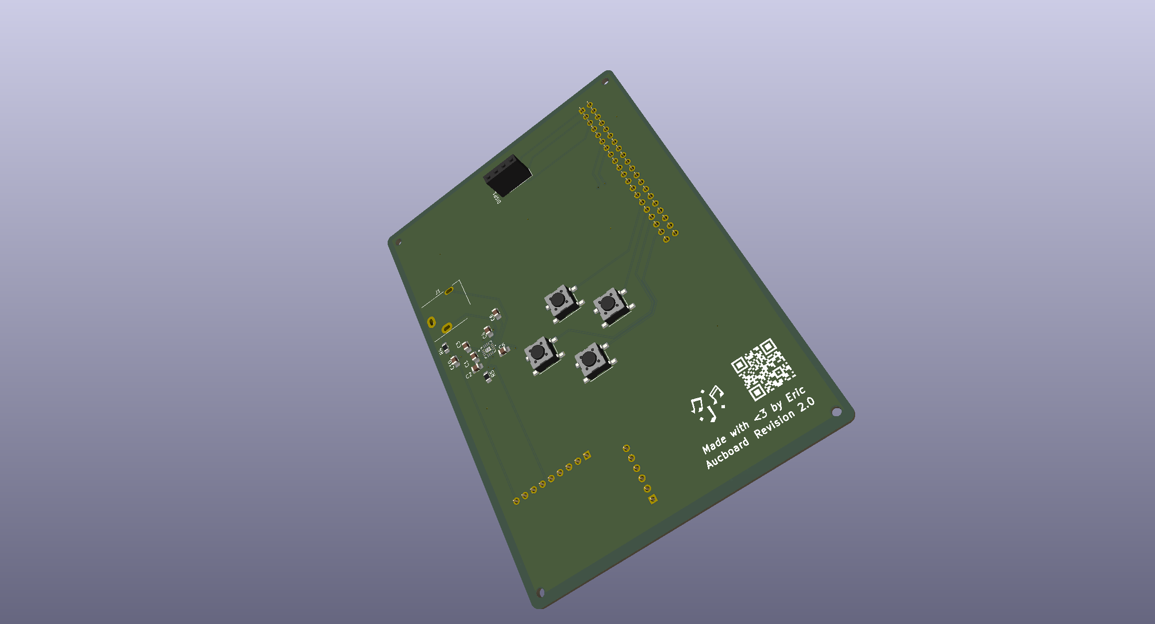 Revision 2 Aucboard
[!NOTE] This is my first ever hardware project involving CAD/PCB design, if there are any issues you can create one: Create an issue
Aucboard in its design aims to provide high fidelity, 384KHz audio to listeners in a small package.
The hardware I am using/have used to make this project possible:
| Link | Supplier/Seller | Approx. Price |
|---|---|---|
| Common PCM5102A DAC breakout board | Amazon AU | ~A$20.39 |
| Raspberry Pi(R) Zero 2 W | Hack Club (find options near you) | ~US$15.00 |
| SSD1306 Monochrome OLED display | Find options near you | ~A$15.00 - ~A$25.00 |
| Total | A$69.89 - A$79.89 |
[!IMPORTANT] For the perspective of Hack Club's Half Life, I have already bought the Common PCM5102A DAC breakout board, Raspberry Pi(R) Zero 2 W and the SSD1306 Monochrome OLED display myself. PCB manufacturing and fabrication costs are going to be receiving the most funding for this project.
Tools used:
The optimal fabrication solution I figured was JLCPCB, as PCBWay can charge $5-10 more per board. If you end up building this yourself, make sure to factor in those costs and whether you'd like PCBA, or manual work. For me, I'll be using PCBA.
This section will go into the design process of the board.
The very simplistic schematic of the board is shown below, as it was in V1 (forgetting DAC2, GPIO27, GPIO22, GPIO17, GPIO23 and AGND, I was setting up layouts for an amplifier)

And a bit of placement magic onto the PCB, including a ground plane with a 0.2 mm clearance, 0.3 mm thermal relief gap and solid pad connections for some shielding:

(The text and barcode was on the F.Cu layer, I didn't know this at the time and I fixed it to F.Silkscreen instead...)
So afterwards, the PCB would look like this:
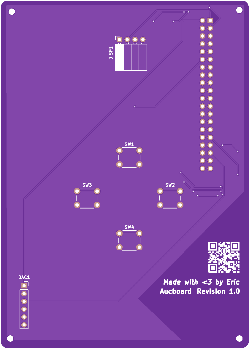
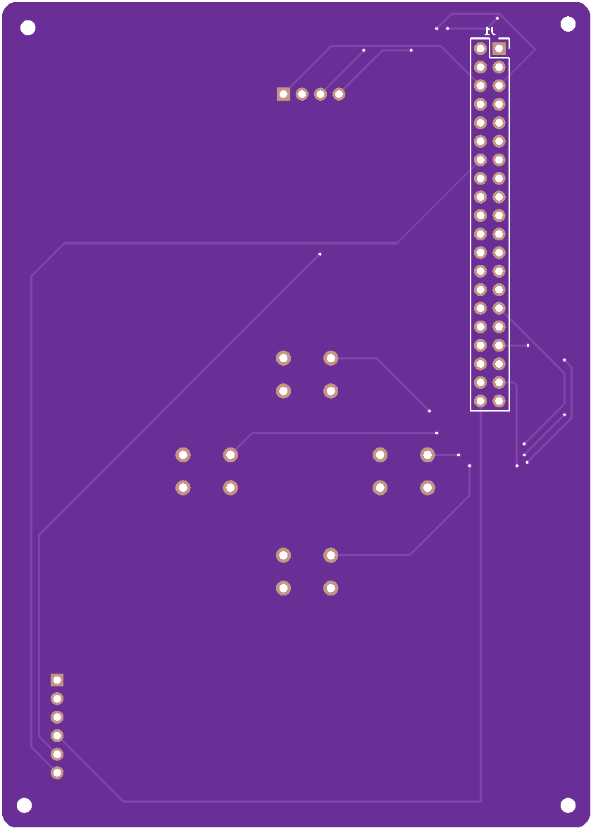
I tried my best to keep the DIN cable routed at the back and short, I wanted minimal crosstalk between the power and signal lines as is typical practice when making boards like this. Constraints required me to use a lot of vias as you can see via the dots on traces (as shown in KiCAD).
This PCB has no real amplification to it. So, the line-level signal coming out from the DAC would actually fail to drive basic headphones properly unfortunately. Another design is needed, and note to self for next time:
In Revision 2.0, I added an amplifier called the MAX97220AETE+T into the mix and moved some things around. I made the buttons surface-mount so it would be way easier for me to route traces properly across the board. Additionally, there are now less vias, making the board way cleaner. This was done over 10 hours of work approximately, most of me was trying to understand the optimal circuit the PDF datasheet recommended. The amp circuit is effectively the same, but I replaced the input smoothing 0.47uF capacitors with 1uF capacitors to allow a decrease in frequency to ~15Hz rather than ~33Hz minimum.

On the PCB, it received a full re-design, including with how components are placed. Now the DAC is flipped around to the other side and rotated, giving easier access for the amplifier circuit to work properly. There are now two (bigger) ground planes stitched to each other instead of just the one, aiming to provide better thermal spreading, better EMI shielding meaning better signal integrity, and lower impedence ground return paths.

The routing spaghetti is definitely less, automatically allowing for greater reliability because not everything is very packed like Revision 1.
The software implemented right now at firmware/ is very basic, and definitely needs greater development. Though, the greatest achievement I'm proud of is how miniaudio plays audio so smoothly on constrained devices. Furthermore, I can edit the audio stream in software rather than constantly configuring a tool like pactl filters.
In the first few commits, pygame was implemented due to its simpler pygame.mixer, but if I kept it like that, audio quality would've been sacrificed heavily for its simplicity. Heavy stuttering and jitter would have occurred for the tests directly because of Python (as the same happens with PyAudio too). Miniaudio simplifies it way down for Aucboard.
This is an ongoing project, and I have not at all started with software yet. This README right now only shows a basic design, where everything may not be up to date as I revise.
| Qty | Value | Footprint | References |
|---|---|---|---|
| 6 | 10k | Resistor_SMD:R_0805_2012Metric_Pad1.20x1.40mm_HandSolder | R1, R2, R3, R4, R5, R6 |
| 5 | 1µF | Capacitor_SMD:C_0805_2012Metric_Pad1.18x1.45mm_HandSolder | C1, C2, C3, C4, C5 |
| 4 | 1uF | Capacitor_SMD:C_0805_2012Metric_Pad1.18x1.45mm_HandSolder | C7, C8, C9, C10 |
| 4 | SW_Push | Button_Switch_SMD:SW_SPST_PTS645Sx43SMTR92 | SW1, SW2, SW3, SW4 |
| 1 | 0.1µF | Capacitor_SMD:C_0805_2012Metric_Pad1.18x1.45mm_HandSolder | C6 |
| 1 | AudioJack3 | Connector_Audio:Jack_3.5mm_CUI_SJ1-3513N_Horizontal | J1 |
| 1 | Conn_01x04_Pin | Connector_PinSocket_2.54mm:PinSocket_1x04_P2.54mm_Vertical | DISP1 |
| 1 | Conn_02x20_Odd_Even | Connector_PinSocket_2.54mm:PinSocket_2x20_P2.54mm_Vertical | RPIZ2W1 |
| 1 | MAX97220AETE+T | MAX97220AETE+T:21-0136I_T1633-4_MXM | U1 |
| 1 | ~ | Connector_PinSocket_2.54mm:PinSocket_1x09_P2.54mm_Vertical | DAC2 |
| 1 | ~ | Connector_PinSocket_2.54mm:PinSocket_1x06_P2.54mm_Vertical | DAC1 |
The 26 most common of 30 parts.
It measures 80.5 × 113 mm and has 2 copper layers, 1.6 mm thick.
30 parts, built around the MAX97220AETE+T. The full list of its parts is on this page, with links to each part's symbol and footprint where PCBKit's library has them.
From the JustAnEric/aucboard repository on GitHub, at the commit this page was made from: the board is pcb/aucboard.kicad_pcb and its schematic pcb/aucboard.kicad_sch. PCBKit opens the board in the browser, with nothing to install.
Its repository states no licence, so its author keeps all rights: ask JustAnEric before reusing the design.
wafaffles/Miniamp
A pocketable DAC/amp based on the PCM2706CPJTR IC. It will be a low power DAC/amp with multiple buttons to be able to easily control media without opening the device.

google/mozc-devices
Circuit diagrams and firmware source code for Gboard DIY keyboards


VoronDesign/Voron-Hardware
Cool Hardware designed by the Voron Design group

hoglet67/RGBtoHDMI
Bare-metal Raspberry Pi project that provides pixel-perfect sampling of Retro Computer RGB/YUV video and conversion to HDMI

tenderlove/initial-v
It's a BMW shifter converted to a Bluetooth Keyboard that you use with Vim

hackclub/OnBoard
💡 Join 1,000 teenagers and make your first PCB with a $100 grant!
