4 layers76.2 × 76.2 mm
Dodekaedri
e-xla/dodekaedri
dodekaedrin muotoinen radio ":D" / dodecahedron shaped radio ":D"
227 parts2
 jurihock/SainSmartFanMod2
SainSmart solder fume extractor modification
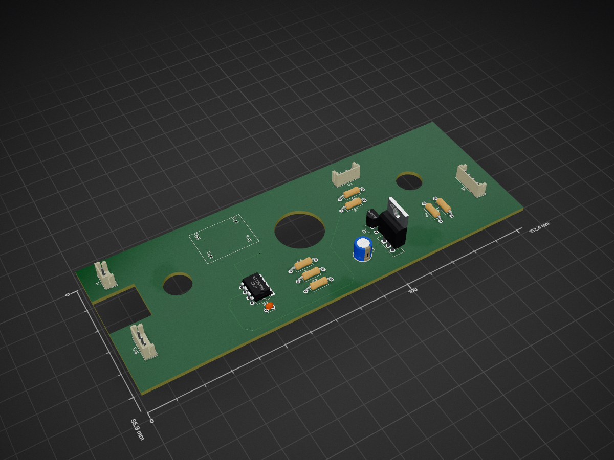
SainSmartFanModKiCad is an open-source printed circuit board by jurihock, from the jurihock/SainSmartFanMod repository on GitHub, published under the GPL-3.0 licence. It is a 2-layer board of 152.4 × 55.9 mm with 20 parts on 16 nets, routed with 78 tracks and 2 vias.
It is built around the ATTINY85-15M and IRL510PBF. Its parts include 7 resistors, 5 connectors, 2 capacitors, 2 transistors and 1 IC. It belongs with the AVR (ATmega, ATtiny) boards of this library.


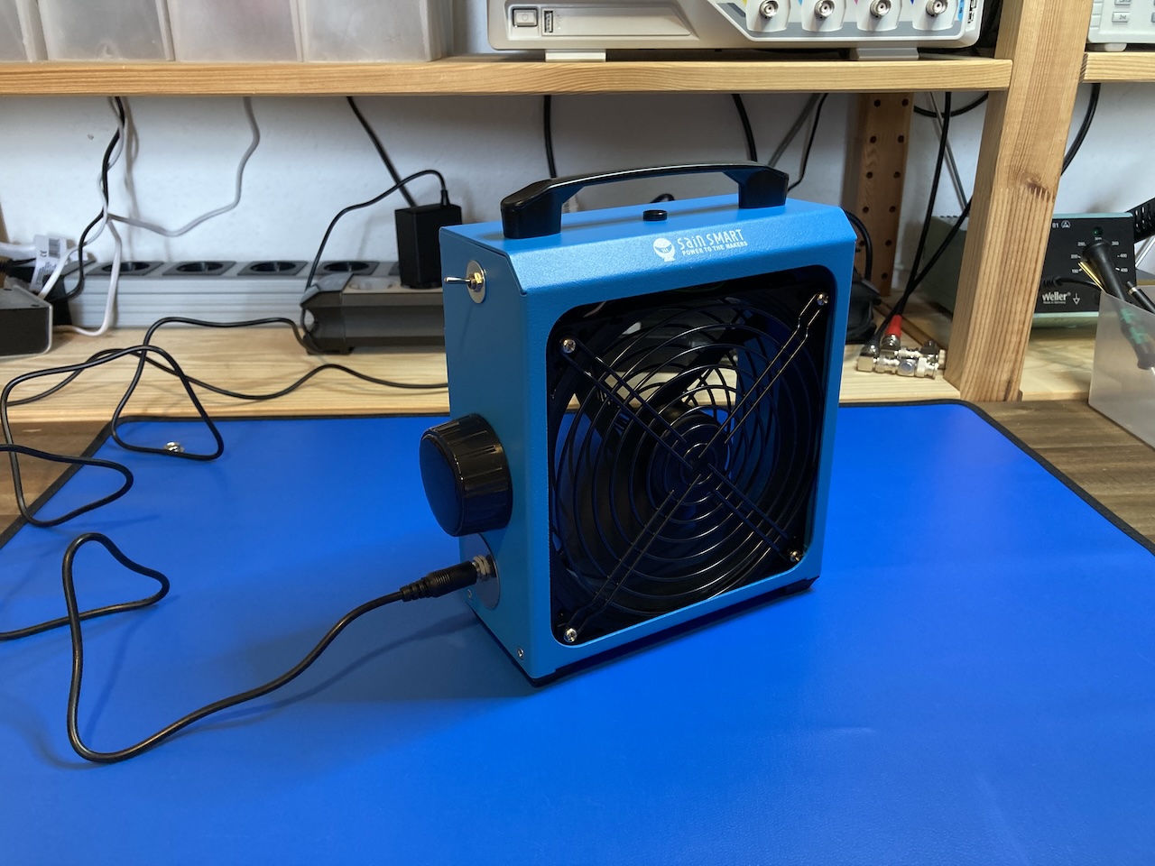
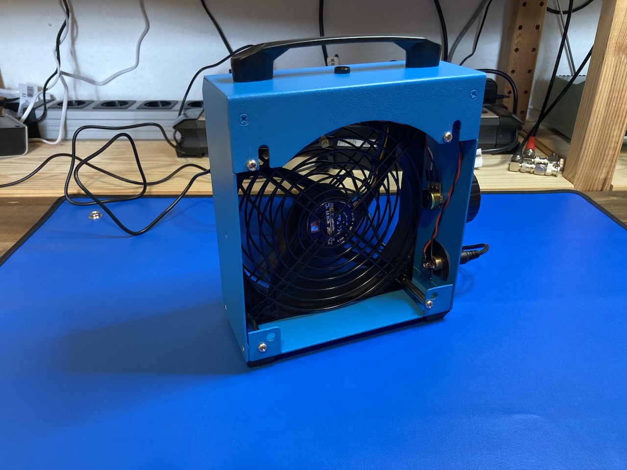
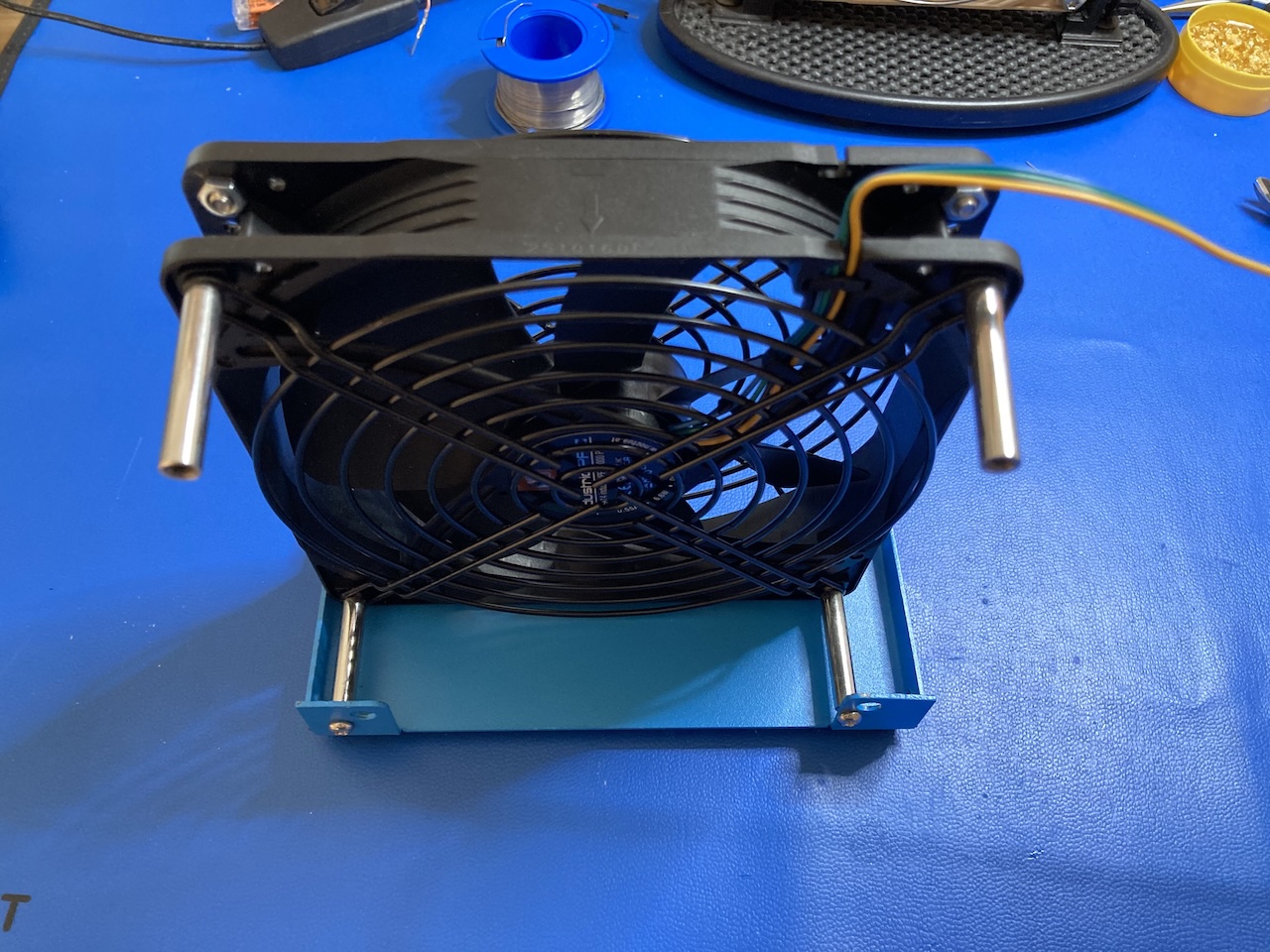
This project is about replacing the default AC fan in the SainSmart solder fume extractor with a DC fan like Noctua NF-A14.
In fact, the Noctua fan draws around 2A during the initial turn. I decided to use a logic-level MOSFET to switch the fan on. Adding a cap between 10uF and 100uF increases the Miller effect, forcing the fan to start up slowly and reducing the initial current as well. But in this case, an NPN transistor is needed to ground the PWM signal against the N-MOSFET drain.
I'm unsure whether a DC fan requires a flyback diode. I decided to skip it for now.
The JST connectors are intentionally placed on the edges, which puts mechanical stress on the board. There is certainly a better solution for connector placement.
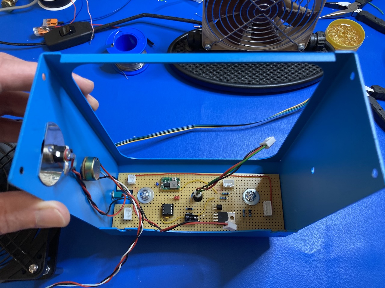
| Qty | Value | Footprint | References |
|---|---|---|---|
| 4 | 10k | Resistor_THT:R_Axial_DIN0207_L6.3mm_D2.5mm_P10.16mm_Horizontal | R1, R3, R6, R7 |
| 3 | 100k | Resistor_THT:R_Axial_DIN0207_L6.3mm_D2.5mm_P10.16mm_Horizontal | R2, R4, R5 |
| 1 | 100n | Capacitor_THT:C_Disc_D3.0mm_W2.0mm_P2.50mm | C2 |
| 1 | 12V PSU | Connector_JST:JST_EH_B2B-EH-A_1x02_P2.50mm_Vertical | J1 |
| 1 | 2N3904 | Package_TO_SOT_THT:TO-92_Inline_Wide | Q2 |
| 1 | 47u | Capacitor_THT:CP_Radial_D6.3mm_P2.50mm | C1 |
| 1 | ATtiny85 | Package_DIP:DIP-8_W7.62mm | U1 |
| 1 | BUCK IN+ | Connector_PinHeader_1.00mm:PinHeader_1x01_P1.00mm_Vertical | J2 |
| 1 | BUCK IN- | Connector_PinHeader_1.00mm:PinHeader_1x01_P1.00mm_Vertical | J3 |
| 1 | BUCK OUT+ | Connector_PinHeader_1.00mm:PinHeader_1x01_P1.00mm_Vertical | J4 |
| 1 | BUCK OUT- | Connector_PinHeader_1.00mm:PinHeader_1x01_P1.00mm_Vertical | J5 |
| 1 | Fan_4pin | Connector_JST:JST_EH_B4B-EH-A_1x04_P2.50mm_Vertical | M1 |
| 1 | IRL510 | Package_TO_SOT_THT:TO-220-3_Vertical | Q1 |
| 1 | LED_Dual_AAK | Connector_JST:JST_EH_B3B-EH-A_1x03_P2.50mm_Vertical | D1 |
| 1 | R_Potentiometer | Connector_JST:JST_EH_B3B-EH-A_1x03_P2.50mm_Vertical | RV1 |
e-xla/dodekaedri
dodekaedrin muotoinen radio ":D" / dodecahedron shaped radio ":D"


cnlohr/ethertiny
A firmware-only half-duplex 10Base-T implementation for AVRs

It measures 152.4 × 55.9 mm and has 2 copper layers, 1.6 mm thick.
20 parts, built around the ATTINY85-15M and IRL510PBF. The full list of its parts is on this page, with links to each part's symbol and footprint where PCBKit's library has them.
From the jurihock/SainSmartFanMod repository on GitHub, at the commit this page was made from: the board is SainSmartFanModKiCad/SainSmartFanModKiCad.kicad_pcb and its schematic SainSmartFanModKiCad/SainSmartFanModKiCad.kicad_sch. PCBKit opens the board in the browser, with nothing to install.
Its repository publishes it under the GPL-3.0 licence: you may reuse it on that licence's terms (keep the author's notice, and for a copyleft licence share your changes alike).