Skip to the content
PCBKitNew board
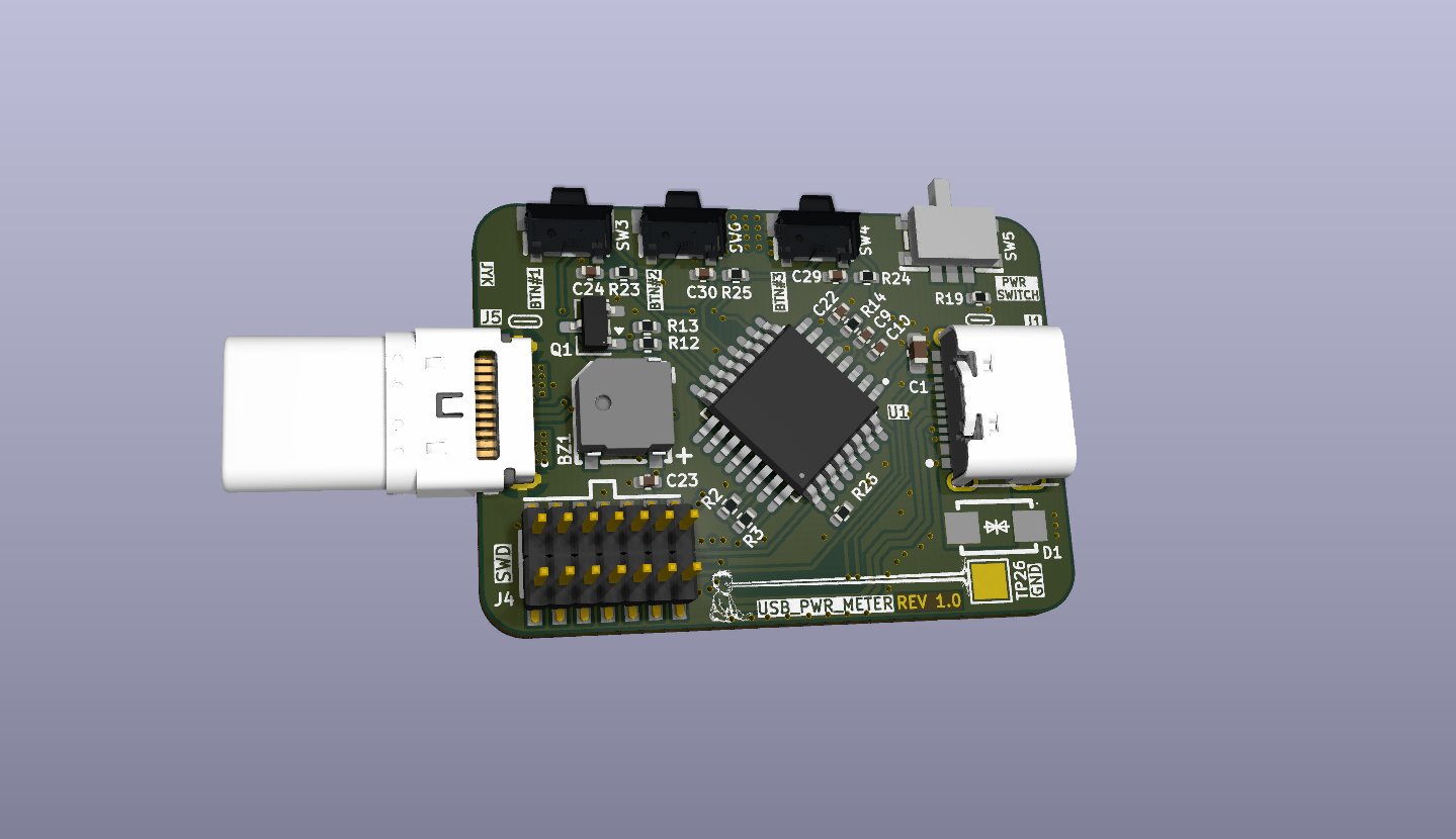
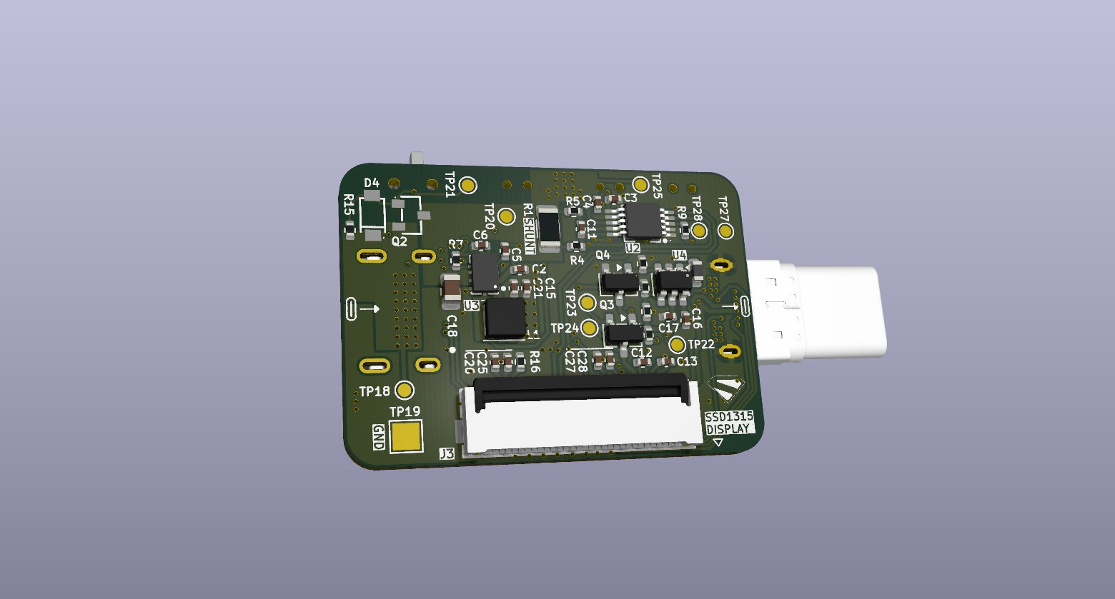
4 layers33.5 × 24 mmUSBPowerMeter, the printed circuit board in 3D

A compact USB-C passthrough power meter that displays real-time voltage, current, and power on an integrated 128×64 OLED screen.

Size
33.5 × 24 mm
Copper layers
4
Thickness
1.6 mm
Parts
84
Nets
80
Pads
301
Tracks, vias
499, 153
Pours
12
Routed
Yes
KiCad
KiCad 10.0 (file 20260206)
Created
11 May 2026
Updated
16 Jun 2026

Overview

USBPowerMeter is an open-source printed circuit board by JunKimmmy, from the JunKimmmy/USBPowerMeter repository on GitHub. It is a 4-layer board of 33.5 × 24 mm with 84 parts on 80 nets, routed with 499 tracks and 153 vias.

It is built around the INA238AIDGSR, LMR36006FSC3RNXRQ1 and MSMCP1640T-I/CHY, with the TS24CA, BRCS5P06MA and BZT52C12 among its other parts. Its parts include 25 capacitors, 21 resistors, 4 ICs, 4 transistors and 4 connectors. It belongs with the STM32 boards of this library.

Main components

11

README

README.md

USB-C Power Meter

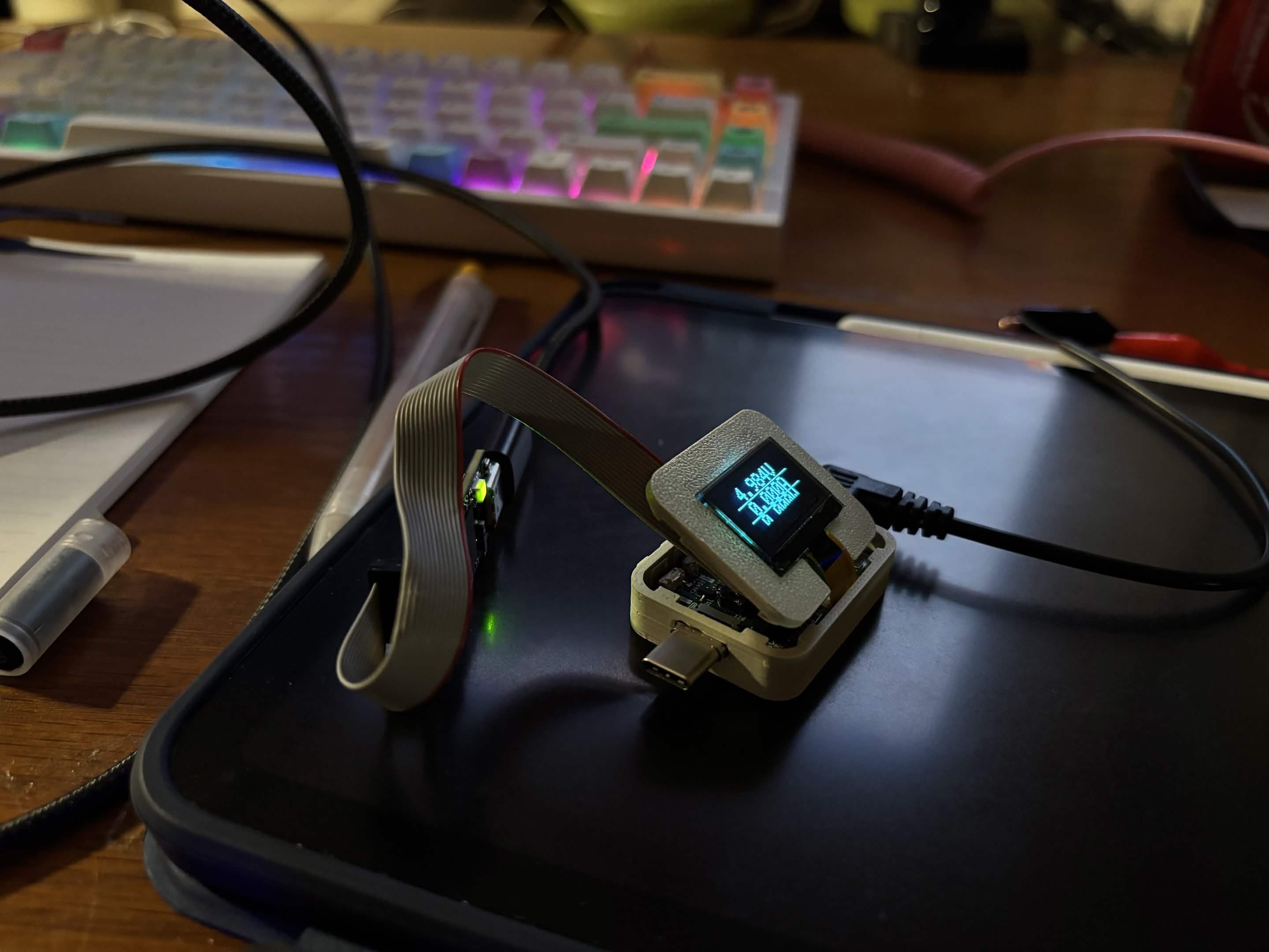
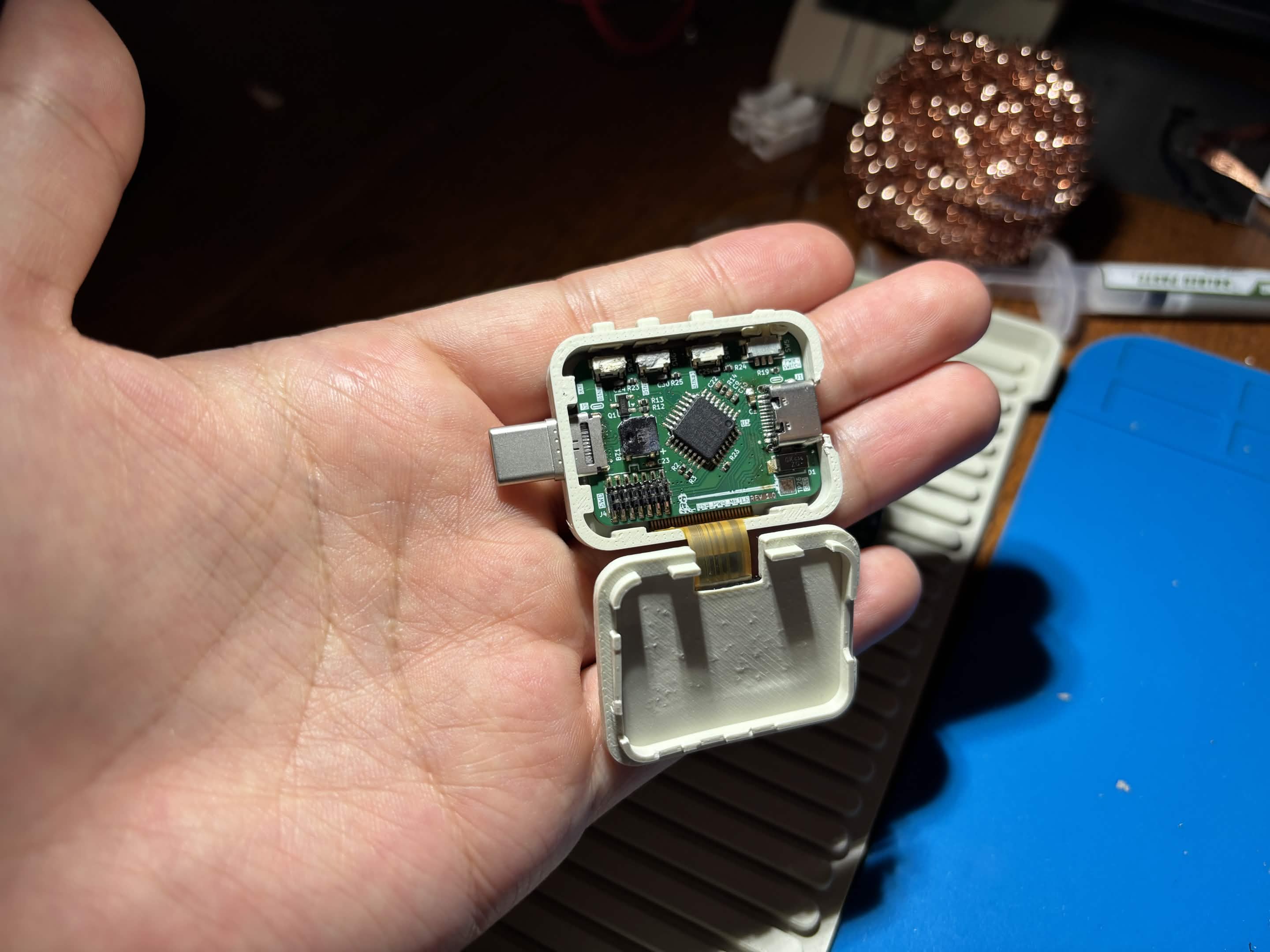
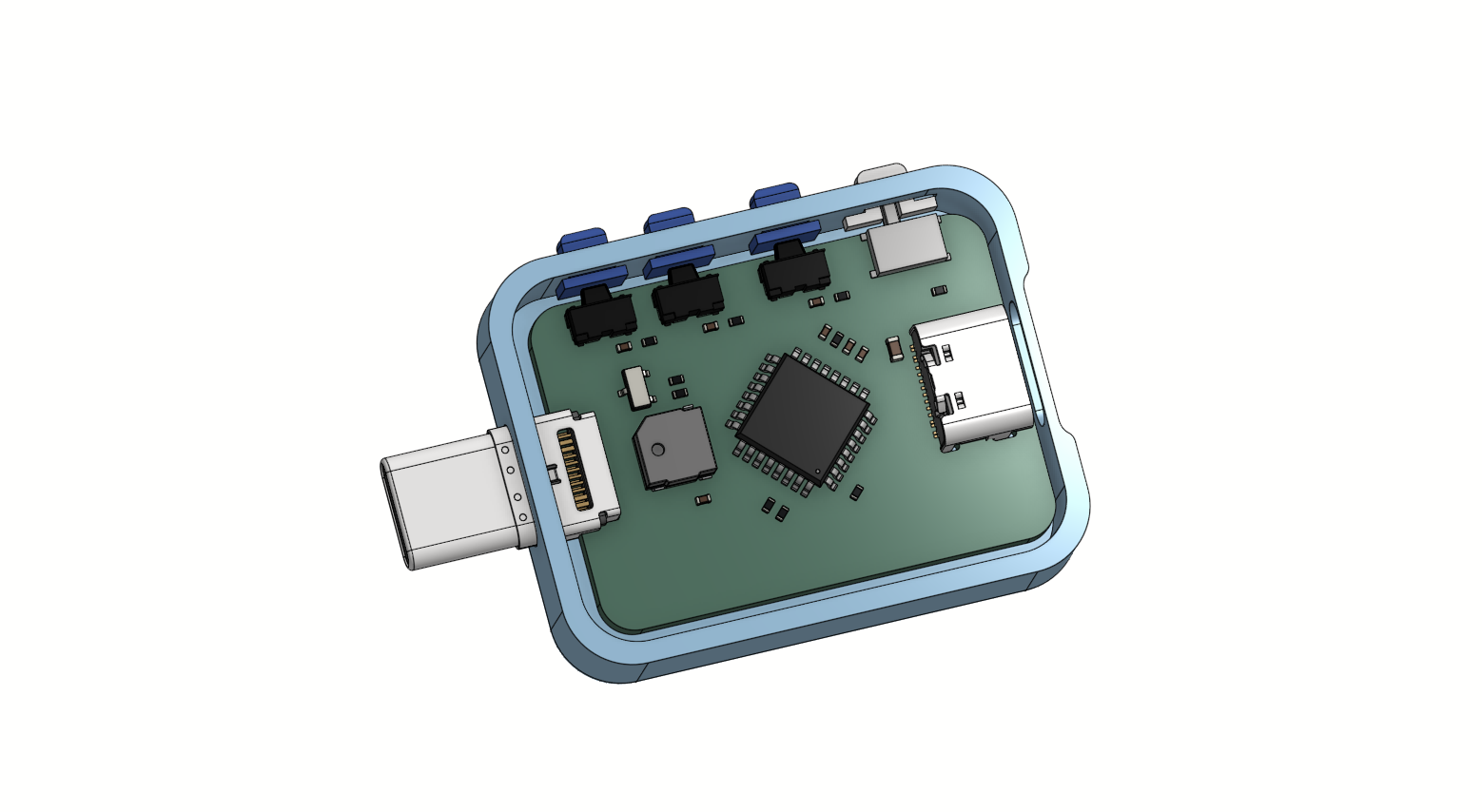
Device running in enclosure PCB inside open enclosure

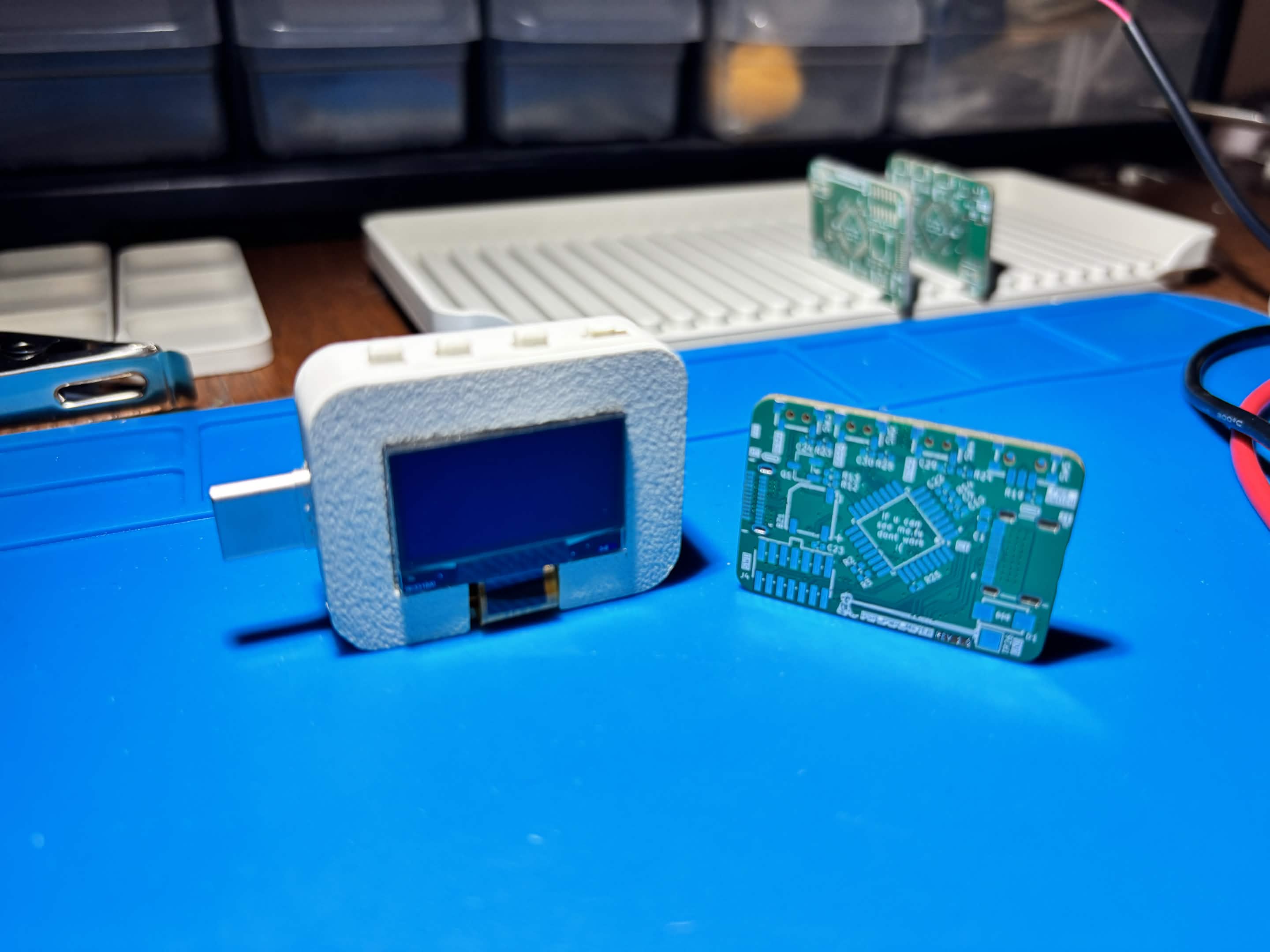
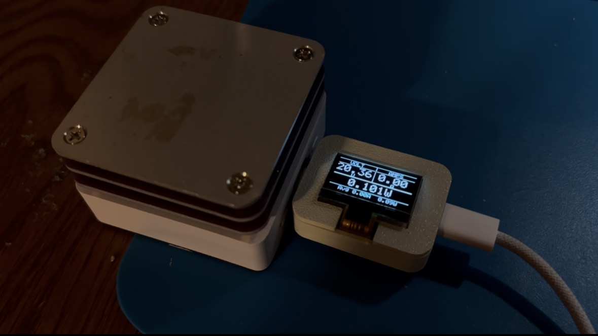
Finished enclosure and bare PCB Device reading power from mini hotplate

A compact USB-C passthrough power meter that displays real-time voltage, current, and power on an integrated 128×64 OLED screen. It sits inline between a USB-C charger and a device — all USB signals pass through transparently while the onboard MCU samples the INA238 power monitor and drives the display.


Features

  • Real-time readout — voltage, current, and power updated continuously
  • Rolling graphs — 128-sample circular-buffer plots for current and power with live, average, and peak annotations
  • Running averages — displayed in the footer of the main meter screen
  • Boot animation and dancing-banana easter egg
  • Buzzer with user-configurable tones and mute toggle
  • Power switch and navigation buttons for menu control
  • Full USB-C signal passthrough (VBUS + data lines)

Specifications

ParameterValue
Input voltage range0.3 V – 48 V
Max continuous current5 A
ADC resolution16-bit (INA238)
Display128×64 OLED (SSD1315), I²C
MCUSTM32G030K6T6 (LQFP-32)
MCU/peripheral supply3.3 V buck from VBUS
OLED supply3.8 V boost
PassthroughUSB-C male + USB-C female

PCB

PCB front — component side PCB back — power supply side

Designed in KiCad 10. All custom symbols and footprints are in libs/.

Key ICs

ICFunction
INA23816-bit high-precision power/current/voltage monitor (shunt + bus voltage)
STM32G030K6T6Measurement processing, graph engine, display control
SSD1315128×64 OLED controller (I²C)
LMR36006VBUS-to-3.3 V synchronous buck regulator
DGS0010A3.8 V boost supply for OLED

Enclosure

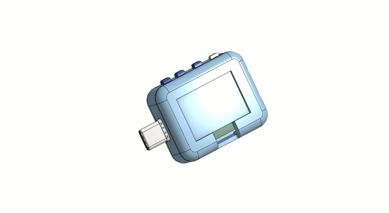
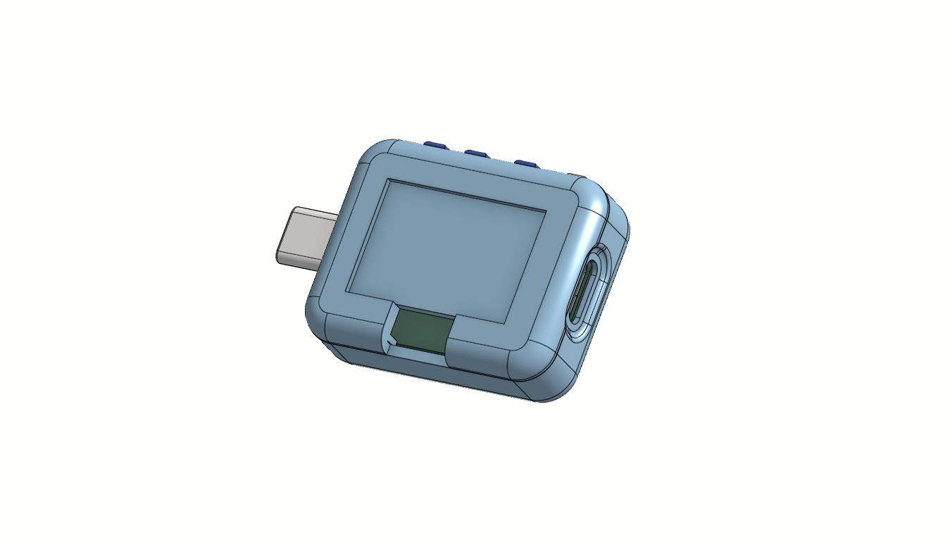
Enclosure front Enclosure side Enclosure open showing PCB

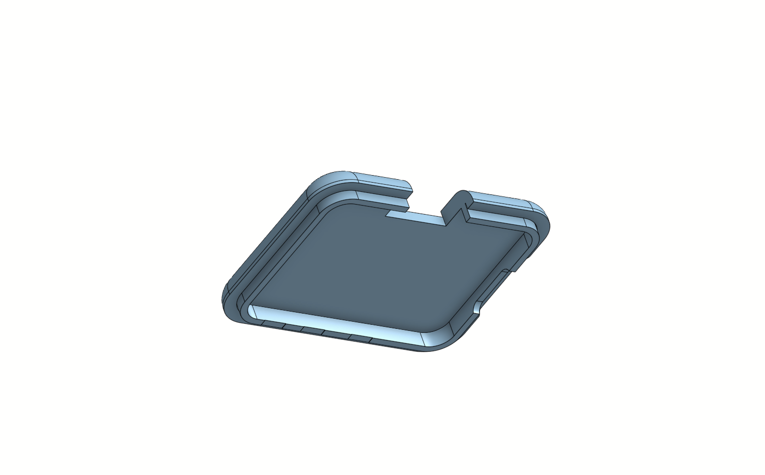
Enclosure lid

3D-printable enclosure designed in OnShape: View in OnShape


Build Process

All components were hand-soldered. Firmware was flashed over SWD using an ST-Link V3 Mini.

PCB sitting in open 3D-printed enclosure ST-Link V3 Mini connected via SWD ribbon for flashing

Videos

VideoDescription
PCB AssemblyHand-soldering all components onto the board
Display TestingOLED display bring-up and meter UI
Buzzer TestingBuzzer tone testing

Testing

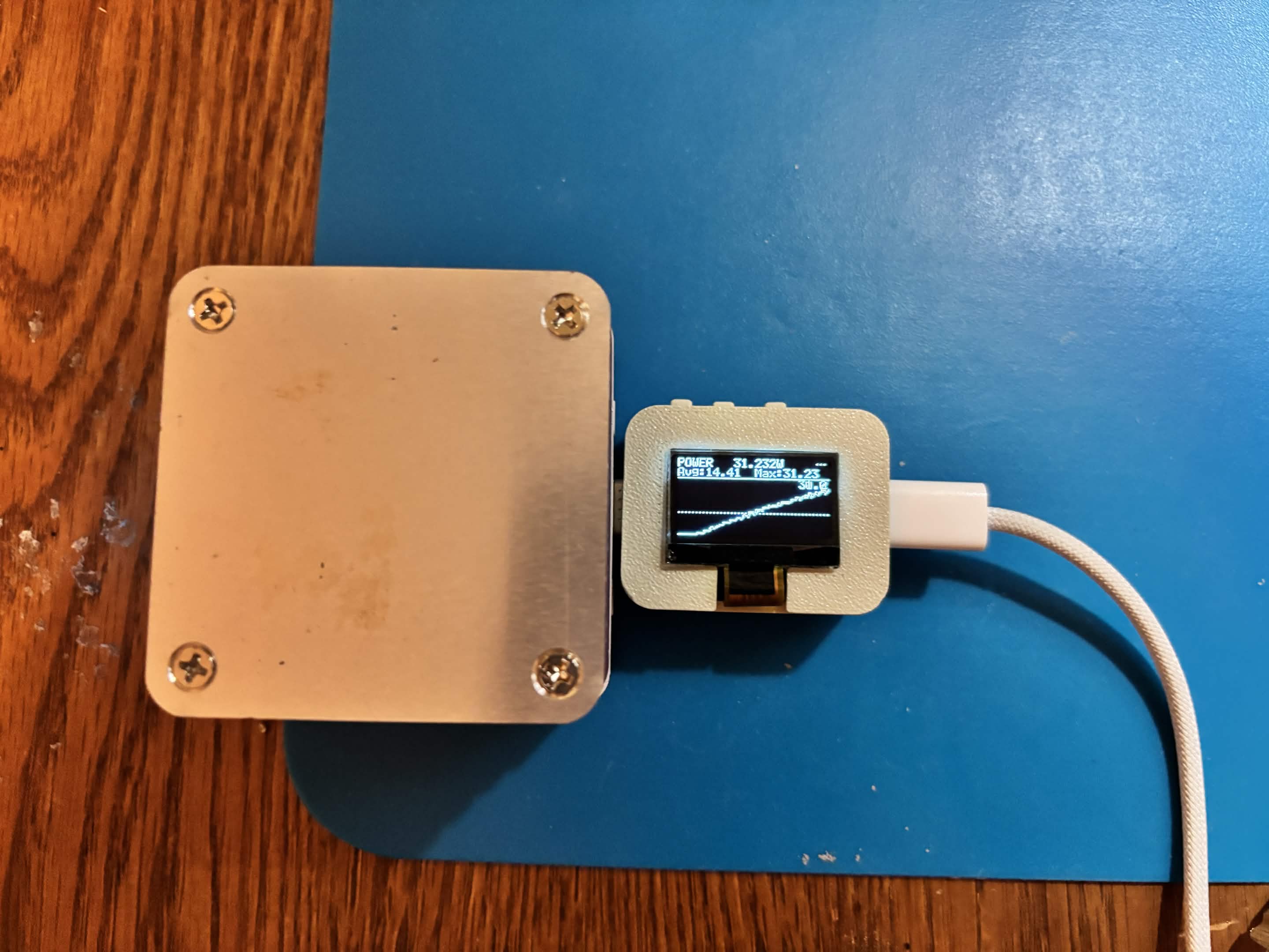
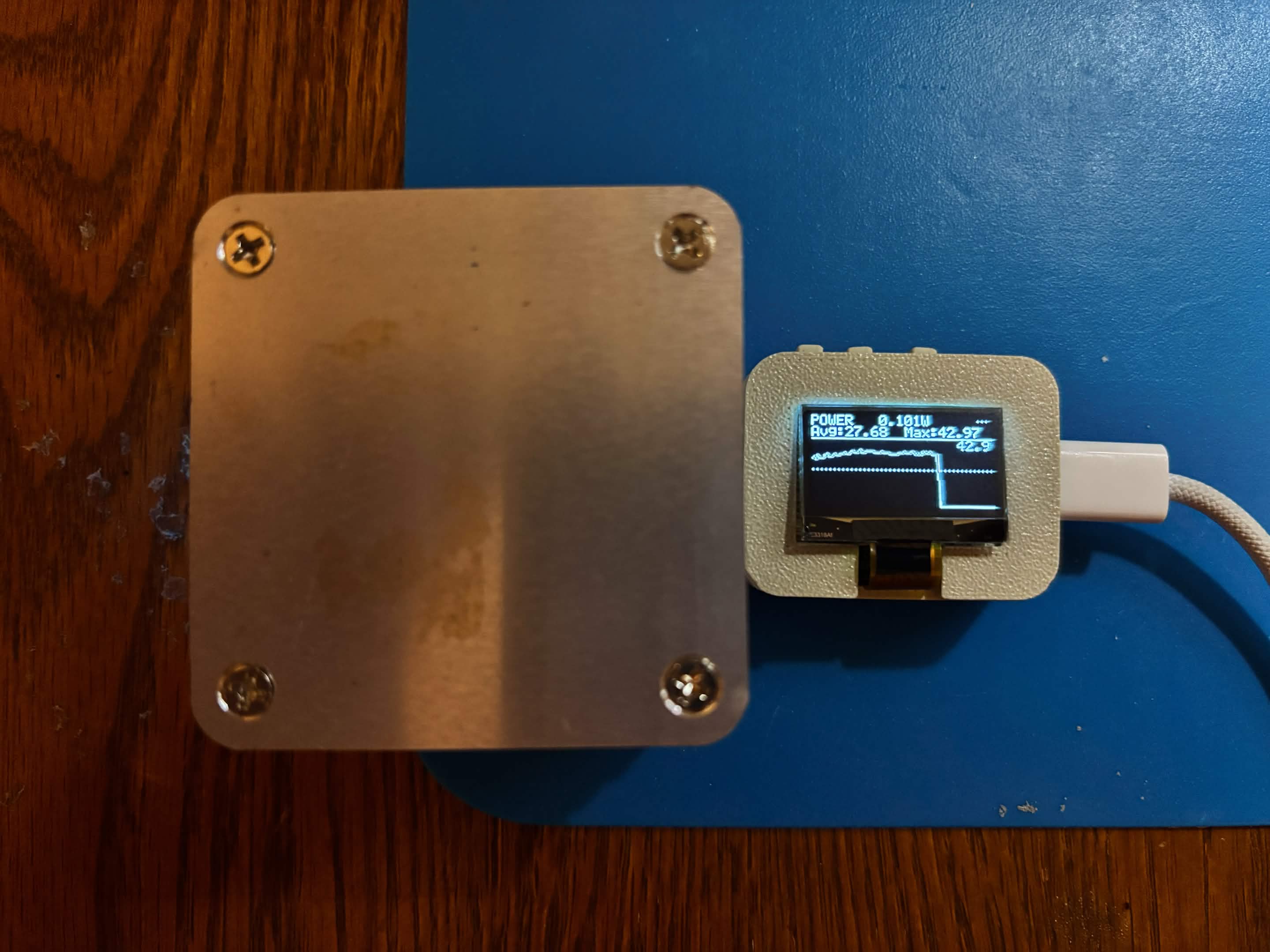
The meter was tested by powering a mini hotplate (~20 V supply). The power graph clearly shows the hotplate's heating element ramping up linearly from 0 W as it heats, plateauing around 42 W once it reaches temperature, then dropping sharply when switched off.

Power graph rising as hotplate heats up Power graph plateauing at ~42 W then dropping when hotplate is switched off

Close-up of meter display during hotplate test


Firmware

Written in C using STM32CubeIDE with the STM32 HAL. Targets the STM32G030K6T6.

Display Modes

ModeDescription
Main MeterTwo-column header (VOLT / AMPS), large 2× readout, full-width power row, footer with running averages
Current Graph128-sample rolling plot of current (mA), dashed line = running average, header shows live + avg + peak
Power GraphSame layout as current graph but for power (mW)

Navigate between modes with the onboard buttons.

Source Modules

FilePurpose
main.cHAL init, main loop, buzzer tone engine
meter.cDisplay screens, graph circular buffer, button debounce
oled.cSSD1315 OLED driver (I²C, page-mode framebuffer)
ina238.cINA238 driver — shunt/bus voltage, current, power registers
boot.cAnimated boot screen
banana.c / banana_frames.cDancing-banana easter egg animation
generate_frames.pyConverts 249×246 GIF PROGMEM bitmaps to SSD1315 page-format C arrays

Building & Flashing

  1. Open Firmware/ST/ in STM32CubeIDE
  2. Build (Ctrl+B) — targets STM32G030K6T6, STM32G030K6TX_FLASH.ld
  3. Connect ST-Link V3 Mini to the SWD header and flash

Repository Structure

text
USBpowermeter.kicad_pro       KiCad project
USBpowermeter.kicad_sch       Schematic
USBpowermeter.kicad_pcb       PCB layout
libs/
  Library.kicad_sym           Custom schematic symbols
  Library.pretty/             Custom footprints
  3dmodels/                   STEP models for 3D viewer
Firmware/ST/
  Core/Src/                   Application source (C)
  Core/Inc/                   Application headers
  Drivers/                    STM32 HAL + CMSIS
  generate_frames.py          Bitmap conversion tool
images/                       PCB renders, enclosure CAD, real photos
videos/                       Assembly and testing footage

Parts

84
QtyValueFootprintReferences
9TP4TestPoint:TestPoint_Pad_D1.0mmTP18, TP20, TP21, TP22, TP23, TP24, TP25, TP27, TP28
81uFCapacitor_SMD:C_0402_1005MetricC2, C4, C6, C10, C12, C13, C27, C28
6100nFCapacitor_SMD:C_0402_1005MetricC3, C5, C9, C11, C22, C23
610kΩResistor_SMD:R_0402_1005MetricR9, R14, R23, R24, R25, R26
6LOGOLOGOG***, G***, G***, G***, G***, G***
410uFCapacitor_SMD:C_0402_1005MetricC15, C16, C17, C21
3100kΩResistor_SMD:R_0402_1005MetricR7, R8, R13
310nFCapacitor_SMD:C_0402_1005MetricC24, C29, C30
3TS24CALibrary:SW-SMD_2P-TS24CASW3, SW4, SW6
210RResistor_SMD:R_0402_1005MetricR4, R5
24.7kΩResistor_SMD:R_0402_1005MetricR2, R3
247kΩResistor_SMD:R_0402_1005MetricR20, R21
2TP5TestPoint:TestPoint_Pad_2.0x2.0mmTP19, TP26
1100nFCapacitor_SMD:C_0603_1608MetricC1
1100ΩResistor_SMD:R_0402_1005MetricR12
110uFCapacitor_SMD:C_0805_2012MetricC18
11MΩResistor_SMD:R_0402_1005MetricR15
12.2uFCapacitor_SMD:C_0402_1005MetricC26
1215kResistor_SMD:R_0402_1005MetricR10
122uHInductor_SMD:L_APV_ANR3015L1
12N7002K_C414015Package_TO_SOT_SMD:SOT-23-3Q1
1330kΩResistor_SMD:R_0402_1005MetricR19
14.7uFCapacitor_SMD:C_0402_1005MetricC25
14.7uHInductor_SMD:L_0603_1608MetricL2
15mΩResistor_SMD:R_1206_3216MetricR1
1620kΩResistor_SMD:R_0402_1005MetricR16
1BRCS5P06MALibrary:SOT-23-3_L2.9-W1.3-P1.90-LS2.4-BRQ2
1BZT52C12Library:SOD-123_L2.7-W1.6-LS3.7-RDD4
1FDN335NPackage_TO_SOT_SMD:SOT-23-3Q4
1FDN338P_C347511Package_TO_SOT_SMD:SOT-23-3Q3
1FPC-05FB-30PH20Library:FPC-SMD_30P-P0.50_FPC-05FB-30PH20J3
1HX PZ1.27-2X7P TPLibrary:HDR-SMD_14P-P1.27_HX-PZ1.27-2X7P-TPJ4
1INA238AIDGSRLibrary:VSSOP-10_L3.0-W3.0-P0.50-LS4.9-BLU2
1LMR36006FSC3RNXRQ1Library:VQFN-12_L3.0-W2.0-P0.65-BL_TI_RNXU3
1MINI MSK12CO2Library:SW-SMD_MSK12CO2SW5
1MLT-5020C94598:BUZ-SMD_L5.0-W5.5-P4.60BZ1
1MSMCP1640T-I/CHYPackage_TO_SOT_SMD:SOT-23-6U4
1SMAJ58CA_C2943847Library:SMA_L4.2-W2.6-LS5.0-BID1
1STM32G030K6T6TRLibrary:LQFP-32_L7.0-W7.0-P0.80-LS9.0-BLU1
1USB4155-03-CLibrary_new:GCT_USB4155-03-C_REVAJ5
1USB4215-03-ALibrary_new:CONN_8p94X6p5X3p16_12L_GCCJ1

Questions

How big is the USBPowerMeter PCB?

It measures 33.5 × 24 mm and has 4 copper layers, 1.6 mm thick.

What parts does the USBPowerMeter use?

84 parts, built around the INA238AIDGSR, LMR36006FSC3RNXRQ1, MSMCP1640T-I/CHY and TS24CA. The full list of its parts is on this page, with links to each part's symbol and footprint where PCBKit's library has them.

Where can I download the USBPowerMeter KiCad files?

From the JunKimmmy/USBPowerMeter repository on GitHub, at the commit this page was made from: the board is USBpowermeter.kicad_pcb and its schematic USBpowermeter.kicad_sch. PCBKit opens the board in the browser, with nothing to install.

Can I use the USBPowerMeter design in my own project?

Its repository states no licence, so its author keeps all rights: ask JunKimmmy before reusing the design.

Similar boards

  • 6 layers78 × 89.5 mmAtx-24pin rev3, the printed circuit board in 3D

    Atx-24pin rev3

    nathanfraske/CEC-Platform

    ONE board file, kept current by the wave (owner directive 2026-07-25: "the current best should be placed into a candidate folder per board and kept current with only one board ideally so we have a reference").

    129 partsApache-2.0
  • 4 layers110 × 80 mmSpin rig controller, the printed circuit board in 3D

    Spin rig controller

    Tinkerbug-Robotics/TinkerRocket

    Model rocket flight computer, ground station, iOS app, and simulation

    170 parts1GPL-3.0
  • 4 layers16 × 44 mmPilkbrain, the printed circuit board in 3D

    Pilkbrain

    cr1tbit/pilkbrain

    The schematic is still a bit messy, just for the reference for now.

    106 parts1
  • 4 layers72.4 × 70.2 mmElpass, the printed circuit board in 3D

    Elpass

    inapp123/elPass_hardware

    超老电子通行证:基于zynq7010的LJ64H034 平板电脑/显示器

    214 partsCERN-OHL-P-2.0
  • 2 layers30.7 × 40.6 mmPLC4UNI MEZANINI, the printed circuit board in 3D

    PLC4UNI MEZANINI

    0sirys/Juan_Pimentel_Electiva_2026_C2

    24 partsMIT
  • 4 layersLBD, the printed circuit board in 3D

    LBD

    chaowoses/LottBespittingDiode

    A high-intensity IR blaster built on the RP2040. Browser-native control over WebSerial, MOSFET-driven IR output, 38kHz NEC modulation. Fully open source.

    50 partsGPL-3.0
  • 4 layers36 × 150 mmMagSense, the printed circuit board in 3D

    MagSense

    jinw06k/MagSense_PCB

    MagSense KiCad PCB project

    59 parts