4 layers140 × 100 mm
Rcm dish controller
jrseti/Dish
Simple controller with toggle switches to move the dish motors
314 partsCC0-1.0

 jrseti/roboclaw-cm4-dc-dish-controller
Satellite dish controller using a ROBOCLAW-2X15A-OEM controlled by a Raspberry Pi CM4 module. Powered by DC battery.
Cm4-robo controller is an open-source printed circuit board by jrseti, from the jrseti/roboclaw-cm4-dc-dish-controller repository on GitHub, published under the MIT licence. It is a 4-layer board of 150 × 100 mm with 292 parts on 313 nets, routed with 2,073 tracks and 924 vias.
It is built around the 74LVC1G07SE-7-MS, TPD4EUSB30DQAR and CL21B106KPQNNNE, with the CC0603KRX7R9BB104, 0402B103K500CT and TPESD0402G12V among its other parts. Its parts include 86 resistors, 75 capacitors, 22 diodes, 22 connectors and 11 ICs. It belongs with the computers and single-board computers and power boards of this library.


A satellite dish controller board in the form of a carrier board for a Raspberry Pi Compute Module 4 (CM4) which commands a Basicmicro RoboClaw 2x15A OEM motor controller. Drives the dish's azimuth and elevation motors. The board runs from a 12.8 V LiFePO4 battery.
Schematic: kicad/cm4-robo-controller.pdf
Simulations: sim/README.md
Tomachie AI reviewed the schematic. Here is the Certificate of Accomplishment. Scored 97/100 (which I think is pretty good).
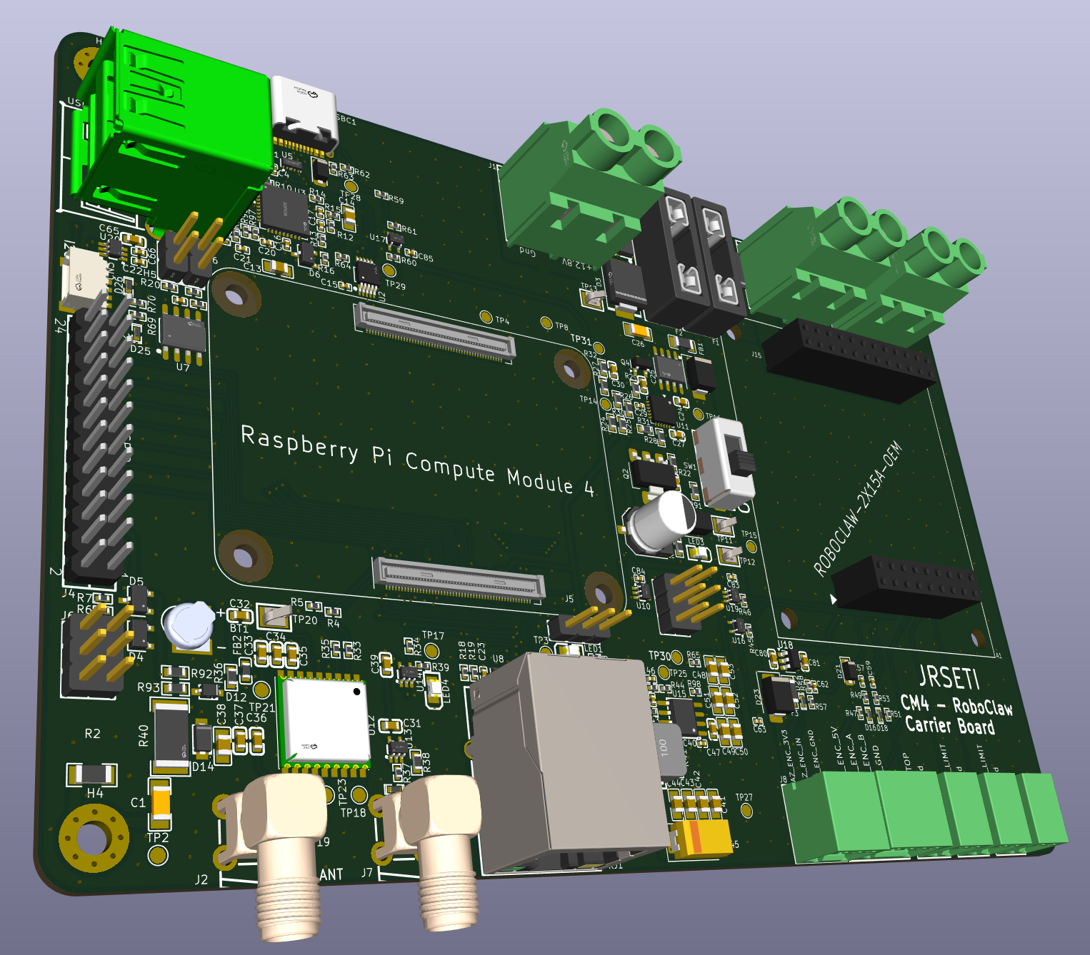
The board combines two modules:
The CM4 decides where the dish should point. The RoboClaw reads the axis sensors and runs the motor control loops.
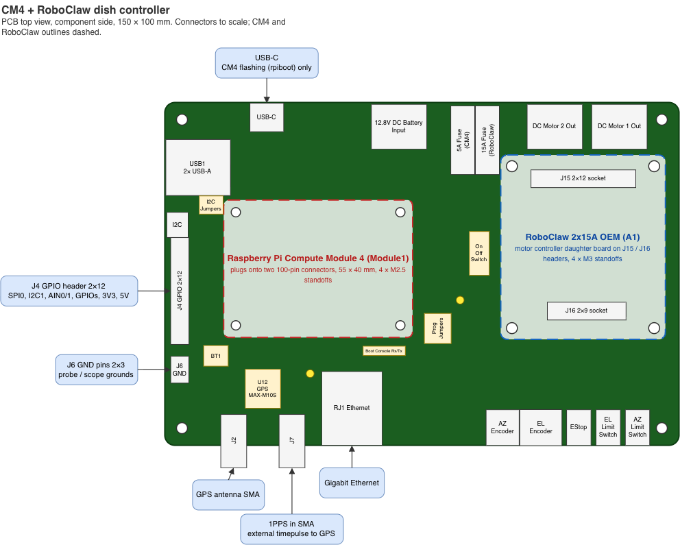
The functional diagram shows the board's layout: the CM4 on the left, the RoboClaw
on the right, and the field connections along the edges. Its source is
drawings/FunctionalDiagram.drawio.
| Axis | Motor | Position sensor | RoboClaw input |
|---|---|---|---|
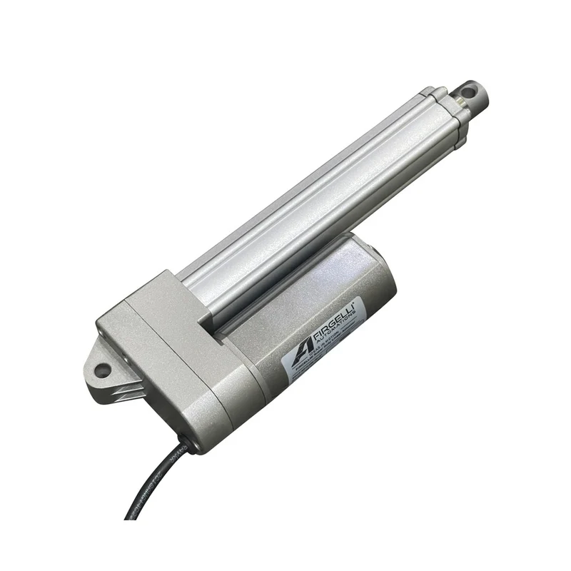
| Elevation (M1) | Firgelli F-SD-H-450-12V linear actuator (5.5 A max, 450 lb) | Built-in Hall sensors, quadrature A/B | EN1 (J8) |
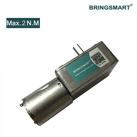
| Azimuth (M2) | Bringsmart JGY-370 12 V worm-gear motor (1.8 A max) | AS5600 magnetic angle sensor, analog output | EN2 (J9) |
Both encoder channels are identical and jumper-configurable, so either axis can use a quadrature encoder (the Firgelli Hall sensors, or an Omron E6B2-CWZ6C open-collector encoder) or an absolute analog encoder (0–2 V at the RoboClaw). Each 4-pin connector carries V+, A (or the analog signal), B and GND, with ESD clamps on both signals.
| Jumper (ENC1 / ENC2) | Shunt | Setting |
|---|---|---|
| JP1 / JP4 — sensor supply (2x3, shunt across a row) | 1-2 | 5 V from the RoboClaw BEC (RC_5V) |
| 3-4 | 3.3 V from the on-board LDO U18 (ENC_3V3) | |
| 5-6 | Battery voltage, 10–14.6 V (ENC_12V: V_MOTOR via a 250 mA PTC, SMAJ20A clamp), e.g. for an E6B2-CWZ6C | |
| JP2 / JP5 — mode (2x3) | 1-3 + 2-4 | QUAD: A gets a 1k pull-up to 5 V and a 100R/10nF filter; B always does |
| 3-5 + 4-6 | ABS: A goes to the analog node (100k/100nF); the pull-up is disconnected | |
| JP3 / JP6 — ABS scaling | 1-2 | 68k/100k divider (×0.6) for a 3.3 V sensor such as the AS5600 |
| 2-3 | 1k series, for a source that already outputs 0–2 V |
Default fit: ENC1 = 5 V, QUAD (Firgelli); ENC2 = 3.3 V, ABS, 3.3 V scaling (AS5600).
docs/encoder-inputs.md explains, part by part, how the channel handles each encoder type: the E6B2-CWZ6C's NPN open-collector outputs, the Firgelli Hall quadrature, and an absolute 0–2 V encoder such as the AS5600.
| Elevation: Firgelli F-SD-H-450 linear actuator | Azimuth: Bringsmart JGY-370 worm-gear motor |
|---|---|
 |  |
The Motor Notes schematic sheet describes the sensor wiring and RoboClaw setup in
detail.
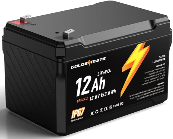
Input: a 12.8 V, 12 Ah LiFePO4 battery (10.0–14.6 V) on J1, a 7.62 mm screw
terminal. The battery is a GoldenMate CRIUS12, IP67 rated, and sits inside the
enclosure. Its manual is in docs/.
Reverse-polarity protection: a P-channel MOSFET (Q1) on the input blocks a battery connected backwards. It still conducts in both directions in normal use, so motor regenerative braking can return energy to the battery.
Fuses: two ATO blade fuses split the supply:
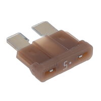
These are ordinary automotive blade fuses, the kind sold for car wiring. They are cheap and available almost anywhere. They plug into Keystone 3557-2 holders, so a blown fuse can be replaced in the field without tools. The board uses Littelfuse 0287005.PXCN (5 A) and 0287015.PXCN (15 A), but any ATO/ATC fuse of the same rating fits.
Q1 is the main protection against a reversed battery. A healthy Q1 blocks the reverse voltage, and no fuse should blow. The fuses are the backup. If Q1 has failed shorted, the reversed battery drives current forward through the input TVS diodes (D1, D3) and the RoboClaw's internal diodes. That current passes through F1 and F2, and the fuses are what stop it. A blown fuse after connecting the battery therefore means: check the polarity, and check Q1, before you fit a new fuse.
The fuses do not cover every reverse fault. If board ground is also connected to the battery's negative terminal by another route, such as a USB device or other equipment that shares the battery, reverse current can flow through the ground wiring and bypass both Q1 and the fuses.
Logic supply: the logic branch goes through a hot-swap eFuse (U11), a power switch (SW1) and a 5 A buck converter (U15). The buck makes 5 V for the CM4 and the USB ports. The CM4's own 3.3 V output powers the 3.3 V logic.
SW1 is not a battery disconnect. It switches the CM4 and logic supply only. With SW1 off the board still draws about 31 mA from the battery: about 30 mA for the RoboClaw's logic, which runs straight from V_MOTOR, plus about 1.3 mA for U11 and its dividers. A full 12 Ah battery runs flat in about 16 days. For storage or transport, unplug J1 (or pull F1 and F2), and charge the battery first. A LiFePO4 battery left at its BMS cutoff for months loses capacity.
Grounding:
rpiboot
(OTG programming of the eMMC).J5 is a 3-pin, 2.54 mm header that brings out the CM4's UART0. It shows bootloader and Linux boot messages and gives a login prompt. That makes it the way into the board when the network is down or the CM4 won't boot.
| J5 pin | Signal | Connect to the adapter's |
|---|---|---|
| 1 | BOOT_CONSOLE_RXD (GPIO15, CM4 receives) | TXD |
| 2 | BOOT_CONSOLE_TXD (GPIO14, CM4 transmits) | RXD |
| 3 | GND | GND |
TX and RX cross over: the adapter's TXD goes to the CM4's RXD.
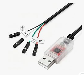
Any inexpensive USB-to-TTL serial cable works. Cables like the one shown, based on the PL2303, CP2102 or FTDI chips, cost a few dollars on Amazon. They usually have four female jumper leads: black GND, white RXD, green TXD and red 5V. Check the labels on your cable.
enable_uart=1 to config.txt. Raspberry Pi OS
already puts console=serial0,115200 in cmdline.txt.BOOT_UART=1 in the EEPROM config with
rpi-eeprom-config.Use a CM4 without wireless and with eMMC, for example CM4004032 (4 GB RAM,
32 GB eMMC) or CM4004016 (16 GB eMMC).
000) cannot
boot on it.The schematic is complete. PCB placement and plane layout are done, and routing is in progress. The software has not been started yet.
| Path | Contents |
|---|---|
kicad/ | KiCad 10 project: schematic sheets and PCB |
parts/ | Git submodule (jrseti/parts): the MyParts symbol, footprint and 3D-model library, its datasheets, and add.py for importing LCSC parts |
docs/ | Component datasheets and design notes |
drawings/ | Draw.io source for the functional diagram |
images/ | Images used in this README |
software/ | CM4 software (not yet started) |
parts/ is a submodule, and the KiCad project needs it to find its symbols,
footprints and 3D models. Clone with:
git clone --recurse-submodules https://github.com/jrseti/roboclaw-cm4-dc-dish-controller.gitIf you have already cloned the repository, run git submodule update --init to
fetch it.
KiCad finds the library through two path variables. Set them in Preferences → Configure Paths:
| Variable | Value |
|---|---|
MYPARTS | <clone>/parts |
MYPARTS_DATASHEETS | <clone>/parts/datasheets |
MIT. See LICENSE.
| Qty | Value | Footprint | References |
|---|---|---|---|
| 23 | TestPoint_Small | MyParts:TestPoint_Pad_D0.8mm | TP1, TP2, TP10, TP14, TP15, TP16, TP17, TP18, TP19, TP21, TP23, TP25, TP26, TP27, TP28, TP29 +7 |
| 21 | 100nF | MyPartsIPC:CAPC1005X55N | C2, C6, C15, C16, C17, C18, C19, C20, C21, C23, C29, C40, C62, C63, C64, C66 +5 |
| 18 | 10uF | MyPartsIPC:CAPC2012X145N | C5, C10, C11, C12, C13, C14, C38, C41, C42, C43, C44, C48, C49, C50, C51, C52 +2 |
| 11 | 100Ω | MyPartsIPC:RESC1005X40N | R4, R5, R33, R35, R37, R45, R46, R49, R53, R103, R106 |
| 11 | 10kΩ | MyPartsIPC:RESC1005X40N | R6, R7, R8, R16, R60, R64, R66, R94, R95, R96, R97 |
| 8 | 100nF | MyPartsIPC:CAPC1608X95N | C24, C25, C27, C31, C34, C35, C39, C47 |
| 7 | 10nF | MyPartsIPC:CAPC1005X55N | C57, C58, C59, C60, C61, C87, C88 |
| 7 | 1kΩ | MyPartsIPC:RESC1005X40N | R34, R47, R51, R100, R102, R104, R105 |
| 6 | Header-Male-2.54_2x3 | MyParts:HDR-TH_6P-P2.54-V-M-R2-C3-S2.54-1 | J3, J6, JP1, JP2, JP4, JP5 |
| 5 | 10kΩ | MyPartsIPC:RESC1608X55N | R24, R25, R31, R36, R93 |
| 5 | 2.2kΩ | MyPartsIPC:RESC1005X40N | R20, R21, R44, R59, R61 |
| 5 | TPESD0402G12V | MyPartsIPC:DIOC1005X55N | D13, D16, D18, D22, D27 |
| 4 | 10uF | MyPartsIPC:CAPC1608X95N | C33, C65, C81, C89 |
| 4 | 20kΩ | MyPartsIPC:RESC1005X40N | R43, R107, R108, R109 |
| 4 | 36kΩ | MyPartsIPC:RESC1005X40N | R12, R13, R14, R15 |
| 4 | 47kΩ | MyPartsIPC:RESC1005X40N | R1, R50, R54, R56 |
| 4 | 74LVC1G17SE-7 | MyPartsIPC:SOT65P210X110-5N | U13, U14, U16, U19 |
| 4 | M3 | MountingHole:MountingHole_3.2mm_M3_Pad_Via | H1, H2, H3, H4 |
| 4 | TPD4EUSB30DQAR | MyPartsIPC:SON50P100X250X60-10N | U5, U6, U8, U9 |
| 3 | 100kΩ | MyPartsIPC:RESC1005X40N | R58, R65, R101 |
| 3 | 1uF | MyPartsIPC:CAPC1608X95N | C30, C32, C80 |
| 3 | 220Ω | MyPartsIPC:RESC1005X40N | R18, R19, R39 |
| 3 | 4.7kΩ | MyPartsIPC:RESC1608X55N | R48, R52, R55 |
| 3 | 74LVC1G07SE-7 | MyPartsIPC:SOT65P210X110-5N | U1, U10, U17 |
| 3 | Header-Male-2.54_1x3 | MyParts:HDR-TH_3P-P2.54-V-M-1 | J5, JP3, JP6 |
| 3 | KF2EDGR-2.54-2P | MyParts:CONN-TH_P2.54_KF2EDGR-2.54-2P | J10, J12, J13 |
| 3 | KF7620-7.62-2P | MyParts:CONN-TH_P7.62_KF7620-7.62-2P | J1, J11, J14 |
| 3 | SMF6.0A | MyPartsIPC:SODFL3718X110N | D8, D21, D24 |
| 3 | TPESD0402G15V | MyPartsIPC:DIOC1005X55N | D17, D19, D20 |
| 2 | 1.5kΩ | MyPartsIPC:RESC1005X40N | R3, R9 |
| 2 | 100kΩ | MyPartsIPC:RESC1608X55N | R11, R38 |
| 2 | 100uF | MyPartsIPC:CAPMP7343X310N | C7, C45 |
| 2 | 12kΩ | MyPartsIPC:RESC1005X40N | R10, R42 |
| 2 | 13kΩ | MyPartsIPC:RESC1608X55N | R26, R30 |
| 2 | 15pF | MyPartsIPC:CAPC1005X55N | C3, C4 |
| 2 | 22Ω | MyPartsIPC:RESC1005X40N | R69, R70 |
| 2 | 33kΩ | MyPartsIPC:RESC1608X55N | R22, R91 |
| 2 | 5.1kΩ | MyPartsIPC:RESC1005X40N | R62, R63 |
| 2 | 68kΩ | MyPartsIPC:RESC1005X40N | R57, R99 |
| 2 | BAT54S | MyPartsIPC:SOT95P280X110-3N | D4, D5 |
| 2 | DF40C-100DS-0.4V(51) | MyParts:DF40C-100DS-0.4V_BOM-ONLY | J17, J18 |
| 2 | GREEN | MyPartsIPC:LEDC2012X110N | LED1, LED3 |
| 2 | KF2EDGR-2.54-4P | MyParts:CONN-TH_4P-P2.54_KF2EDGR-2.54-4P | J8, J9 |
| 2 | SMA-KWE_C7498154 | MyParts:SMA-TH_SMA-KWE_C7498154 | J2, J7 |
| 2 | SMAJ20A | MyPartsIPC:DIOM5226X244N | D11, D28 |
| 2 | SMCJ18A_C53260906 | MyPartsIPC:DIOM7959X262N | D1, D3 |
| 2 | TPESD0402G05V | MyPartsIPC:DIOC1005X55N | D25, D26 |
| 1 | 1.2nF | MyPartsIPC:CAPC1005X55N | C56 |
| 1 | 100mA | MyPartsIPC:FUSC3216X110N | F3 |
| 1 | 10nF | MyPartsIPC:CAPC1608X95N | C37 |
| 1 | 10uF | MyPartsIPC:CAPC3216X180N | C26 |
| 1 | 10Ω | MyPartsIPC:RESC3216X70N | R41 |
| 1 | 120Ω@100MHz | MyPartsIPC:INDC3216X130N | FB1 |
| 1 | 120Ω@100MHz | MyPartsIPC:INDC1608X95N | FB2 |
| 1 | 12V | MyParts:TESTPOINT-SMD_L3.0-W2.0 | TP12 |
| 1 | 15A | MyParts:FUSE-TH_4P-L19.8-W6.7_3557-2 | F1 |
| 1 | 15kΩ | MyPartsIPC:RESC1005X40N | R17 |
| 1 | 174kΩ | MyPartsIPC:RESC1005X40N | R98 |
| 1 | 180kΩ | MyPartsIPC:RESC1608X55N | R27 |
| 1 | 1MΩ | MyPartsIPC:RESC3216X70N | R2 |
| 1 | 1N4148WS T4 | MyPartsIPC:SOD2513X110N | D12 |
| 1 | 210S-1*2P L=11.6MMGold-plated black | MyParts:HDR-TH_2P-P2.54-V-M-1 | H5 |
| 1 | 220uF | MyPartsIPC:CAPAE660X770N | C28 |
| 1 | 24MHz | MyParts:CRYSTAL-SMD_4P-L3.2-W2.5-BL | X1 |
| 1 | 250mA | MyPartsIPC:FUSC3216X110N | F4 |
| 1 | 2541WV-2X12P | MyParts:HDR-TH_24P-P2.54-V-M-R2-C12-S2.54 | J4 |
| 1 | 27nH | MyPartsIPC:INDC1005X55N | L1 |
| 1 | 3.3uH | MyPartsIPC:INDM7366X280N | L2 |
| 1 | 330kΩ | MyPartsIPC:RESC1608X55N | R29 |
| 1 | 330Ω | MyPartsIPC:RESC1608X55N | R92 |
| 1 | 33pF | MyPartsIPC:CAPC1005X55N | C55 |
| 1 | 33Ω | MyPartsIPC:RESC6332X70N | R40 |
| 1 | 3KΩ | MyPartsIPC:RESC1608X55N | R23 |
| 1 | 4.7nF | MyPartsIPC:CAPC3216X180N | C1 |
| 1 | 4.7uF | MyPartsIPC:CAPC1005X55N | C22 |
| 1 | 470pF | MyPartsIPC:CAPC1005X55N | C46 |
| 1 | 47nF | MyPartsIPC:CAPC1608X95N | C82 |
| 1 | 47pF | MyPartsIPC:CAPC1608X95N | C36 |
| 1 | 56kΩ | MyPartsIPC:RESC1608X55N | R32 |
| 1 | 5A | MyParts:FUSE-TH_4P-L19.8-W6.7_3557-2 | F2 |
The 254 most common of 292 parts.
jrseti/Dish
Simple controller with toggle switches to move the dish motors


sire234/VatPoeToUsb
Ein Gerät, das über ein Ethernet-Kabel mit PoE (IEEE 802.3af) gespeist wird und an einem USB-A-Host-Port ein HID-Gerät (Tastatur, Barcode-Scanner, Maus) betreibt. Die HID-Daten stellt die Firmware über Ethernet bereit.


jrseti/dishy1pi
Satellite dish motor control for Raspberry Pi, hardware and software


klaus-liebler/labathome
Der kleine Bruder von lab@home. Ermöglicht das Experimentieren mit PT1...PTn-Gliedern, die intern als RC-Kombination (entkoppelt über Operationsverstärker) ausgeführt sind.
It measures 150 × 100 mm and has 4 copper layers, 1.6 mm thick.
292 parts, built around the 74LVC1G07SE-7-MS, TPD4EUSB30DQAR, CL21B106KPQNNNE and CC0603KRX7R9BB104. The full list of its parts is on this page, with links to each part's symbol and footprint where PCBKit's library has them.
From the jrseti/roboclaw-cm4-dc-dish-controller repository on GitHub, at the commit this page was made from: the board is kicad/cm4-robo-controller.kicad_pcb and its schematic kicad/RCM4.kicad_sch. PCBKit opens the board in the browser, with nothing to install.
Its repository publishes it under the MIT licence: you may reuse it on that licence's terms (keep the author's notice, and for a copyleft licence share your changes alike).