4 layers205 × 140 mm
 jpdb0605/integral
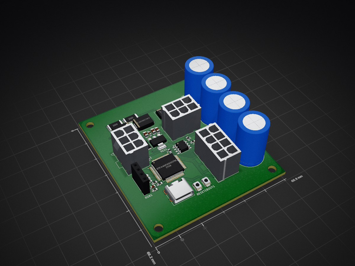
Controle valvula tractus is an open-source printed circuit board by jpdb0605, from the jpdb0605/integral repository on GitHub. It is a 2-layer board of 60.9 × 68.2 mm with 61 parts on 77 nets, routed with 311 tracks and 24 vias.
It is built around the TLV2372IP and AMS1117-3.3. Its parts include 25 resistors, 18 capacitors, 3 diodes, 1 IC and 1 connector.


| Qty | Value | Footprint | References |
|---|---|---|---|
| 11 | 10K | Resistor_SMD:R_0603_1608Metric | R1, R4, R5, R6, R10, R14, R17, R20, R21, R22, R23 |
| 7 | 100nF | Capacitor_SMD:C_0603_1608Metric | C1, C3, C5, C6, C7, C9, C13 |
| 4 | 20 | Resistor_SMD:R_2512_6332Metric | R18, R19, R24, R25 |
| 4 | 4.7F | Capacitor_THT:C_Radial_D12.5mm_H20.0mm_P5.00mm | C15, C16, C17, C18 |
| 3 | 330 | Resistor_SMD:R_0603_1608Metric | R11, R12, R13 |
| 2 | 1K | Resistor_SMD:R_0603_1608Metric | R2, R16 |
| 2 | 20K | Resistor_SMD:R_0603_1608Metric | R3, R9 |
| 2 | 4.7uF | Capacitor_SMD:C_0603_1608Metric | C2, C4 |
| 2 | 5.1K | Resistor_SMD:R_0603_1608Metric | R7, R8 |
| 2 | D_Schottky | Diode_SMD:D_SMC | D1, D2 |
| 2 | SW_Push | Button_Switch_SMD:SW_SPST_B3U-1000P | BOOT1, RESET1 |
| 1 | 100nF | Capacitor_SMD:C_0805_2012Metric | C11 |
| 1 | 10uF | Capacitor_SMD:C_1206_3216Metric | C14 |
| 1 | 10uF | Capacitor_SMD:C_0805_2012Metric | C8 |
| 1 | 1uF | Capacitor_SMD:C_0603_1608Metric | C12 |
| 1 | 2.5A PTC | Fuse:Fuse_1812_4532Metric | F1 |
| 1 | 22uF | Capacitor_SMD:C_0805_2012Metric | C10 |
| 1 | 30K | Resistor_SMD:R_0603_1608Metric | R15 |
| 1 | AMS1117-3.3 | Package_TO_SOT_SMD:SOT-223-3_TabPin2 | REG1 |
| 1 | Conn_01x04 | Connector_PinSocket_2.54mm:PinSocket_1x04_P2.54mm_Vertical | RGB1 |
| 1 | Conn_02x03_Top_Bottom | Connector_Molex:Molex_Mini-Fit_Jr_5566-06A_2x03_P4.20mm_Vertical | YF-B1|POT1 |
| 1 | Conn_02x04_Top_Bottom | Connector_Molex:Molex_Mini-Fit_Jr_5566-08A_2x04_P4.20mm_Vertical | DISPLAY1 |
| 1 | D_Zener | Diode_SMD:D_SMA | D3 |
| 1 | FONTE|VALVE | Connector_Molex:Molex_Mini-Fit_Jr_5566-06A_2x03_P4.20mm_Vertical | J1 |
| 1 | R7FA4M1AB3CFM_AA0 | R7FA4M1AB3CFM_AA0:QFP50P1200X1200X170-64N | U1 |
| 1 | TLV2372 | Package_SO:SOIC-8_3.9x4.9mm_P1.27mm | AMP1 |
| 1 | USB_C_Receptacle_USB2.0_16P | Connector_USB:USB_C_Receptacle_HRO_TYPE-C-31-M-12 | USB-C1 |
The 57 most common of 61 parts.
It measures 60.9 × 68.2 mm and has 2 copper layers, 1.6 mm thick.
61 parts, built around the TLV2372IP and AMS1117-3.3. The full list of its parts is on this page, with links to each part's symbol and footprint where PCBKit's library has them.
From the jpdb0605/integral repository on GitHub, at the commit this page was made from: the board is Tractus/Controle de Válvula/Arquivos/Sistema com placa/controle_valvula_tractus/controle_valvula_tractus.kicad_pcb and its schematic Tractus/Controle de Válvula/Arquivos/Sistema com placa/controle_valvula_tractus/controle_valvula_tractus.kicad_sch. PCBKit opens the board in the browser, with nothing to install.
Its repository states no licence, so its author keeps all rights: ask jpdb0605 before reusing the design.

Moragor/BatteryAnalyzer_MkII
Updated Version of the battery analyzer, now with constant current


devjamescollier/STM-32_Based_Waveform_Generator
USB-powered programmable function generator built around an STM32C031K6T6 microcontroller and MCP4901 DAC. Generates clean sine, triangle, and square waveforms with amplitude control via potentiometer, mode selection…

dnz1666/impedance-buffer-pcb
Analog circuit design (impedance buffer + LP filter) – KiCad schematic & PCB layout for a student EV project at RWTH Aachen


jensboe/Modellbahn
columns 1 block:selfmade block:base columns 1 nucleo adapter["adapter board A"] end space expansion1["expansion board A 1"] space expansionn["expansion board A n"] space expansionb["expansion board B"] adapter…

jkbkwcn/harm_meas_using_os
An electronic circuit project designed to measure mains current harmonics with amplitudes below one Least Significant Bit (LSB) of an Analog-to-Digital Converter.