2 layers41.5 × 42.8 mm

 joshajohnson/rf-sig-gen53
MAX2871 based RF Signal Generator in an Adafruit Feather Form Factor
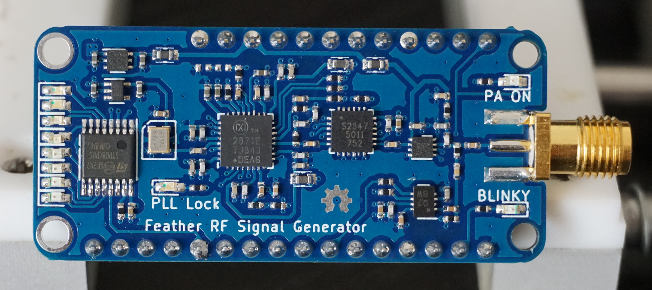
Rf sig gen is an open-source printed circuit board by joshajohnson, from the joshajohnson/rf-sig-gen repository on GitHub. It is a 4-layer board of 50 × 22.9 mm with 91 parts on 83 nets, routed with 663 tracks and 165 vias.
It is built around the MAX2871ETJ+, SKY12347-362LF and STP08CP05M. Its parts include 43 capacitors, 20 resistors, 11 diodes, 7 ICs and 2 connectors. It belongs with the radio and wireless boards of this library.


| Qty | Value | Footprint | References |
|---|---|---|---|
| 11 | LED | LED_SMD:LED_0603_1608Metric_Castellated | D1, D2, D3, D4, D5, D6, D7, D8, D9, D10, D11 |
| 10 | 100p | Capacitor_SMD:C_0402_1005Metric | C7, C9, C11, C13, C16, C18, C20, C28, C34, C42 |
| 9 | 10n | Capacitor_SMD:C_0402_1005Metric | C5, C6, C8, C10, C12, C15, C17, C31, C35 |
| 7 | 1u | Capacitor_SMD:C_0402_1005Metric | C2, C3, C4, C14, C19, C21, C25 |
| 5 | 100n | Capacitor_SMD:C_0402_1005Metric | C1, C23, C27, C41, C43 |
| 5 | 1n | Capacitor_SMD:C_0402_1005Metric | C22, C30, C37, C39, C40 |
| 4 | 1K | Resistor_SMD:R_0402_1005Metric | R9, R10, R16, R19 |
| 4 | 600R | josh-passives-smt:Ferrite_Bead_0603 | FB1, FB2, FB3, FB4 |
| 3 | 49R9 | Resistor_SMD:R_0402_1005Metric | R4, R13, R17 |
| 2 | 0R0 | Resistor_SMD:R_0402_1005Metric | R2, R3 |
| 2 | 47n | Capacitor_SMD:C_0402_1005Metric | C33, C38 |
| 1 | 100R | Resistor_SMD:R_0402_1005Metric | R14 |
| 1 | 100n | Inductor_SMD:L_0402_1005Metric | L1 |
| 1 | 10K | Resistor_SMD:R_0402_1005Metric | R18 |
| 1 | 10p | Capacitor_SMD:C_0402_1005Metric | C36 |
| 1 | 12n | Capacitor_SMD:C_0402_1005Metric | C24 |
| 1 | 18K | Resistor_SMD:R_0402_1005Metric | R11 |
| 1 | 1R8 | Resistor_SMD:R_0402_1005Metric | R15 |
| 1 | 240R | Resistor_SMD:R_0402_1005Metric | R8 |
| 1 | 2K2 | Resistor_SMD:R_0402_1005Metric | R20 |
| 1 | 31R1 | Resistor_SMD:R_0402_1005Metric | R6 |
| 1 | 52R3 | Resistor_SMD:R_0402_1005Metric | R12 |
| 1 | 5K1 | Resistor_SMD:R_0402_1005Metric | R1 |
| 1 | 820p | Capacitor_SMD:C_0402_1005Metric | C29 |
| 1 | 8p2 | Capacitor_SMD:C_0402_1005Metric | C32 |
| 1 | 90R9 | Resistor_SMD:R_0402_1005Metric | R5 |
| 1 | AD8319 | Package_DFN_QFN:DFN-8-1EP_2x3mm_P0.5mm_EP0.61x2.2mm | U6 |
| 1 | ASTXR-12-19.200MHz | josh-oscillators:ASTXR-12 | XO1 |
| 1 | DNP | Capacitor_SMD:C_0402_1005Metric | C26 |
| 1 | DNP | Resistor_SMD:R_0402_1005Metric | R7 |
| 1 | Feather | josh-connectors:featherwing-short | J1 |
| 1 | LOGO | josh-logos:OSHW_Logo_3.6x3.6_F.Mask | G*** |
| 1 | LP5912 | Package_DFN_QFN:DFN-6-1EP_2x2mm_P0.65mm_EP1x1.6mm | U2 |
| 1 | MAX2871 | josh-dfn-qfn:QFN-32-1EP_5x5mm_Pitch0.5mm_Thermal_Vias | U1 |
| 1 | MIC5366-1.8 | Package_TO_SOT_SMD:SOT-353_SC-70-5 | U3 |
| 1 | SKY12347-362LF | Package_DFN_QFN:QFN-24-1EP_4x4mm_P0.5mm_EP2.7x2.7mm_ThermalVias | U4 |
| 1 | SMA | josh-connectors:SMA_EDGE_MOUNT_INSET | J2 |
| 1 | STP08CP05 | Package_SO:TSSOP-16_4.4x5mm_P0.65mm | U7 |
| 1 | TRF37A75 | Package_DFN_QFN:DFN-8-1EP_2x2mm_P0.5mm_EP0.9x1.5mm | U5 |
The 90 most common of 91 parts.

lens42/D-Lev-All-in-One-PCB
This integrates the excellent D-Lev digital theremin design at D-Lev.com into a single surface mount PCB


It measures 50 × 22.9 mm and has 4 copper layers, 1.6 mm thick.
91 parts, built around the MAX2871ETJ+, SKY12347-362LF and STP08CP05M. The full list of its parts is on this page, with links to each part's symbol and footprint where PCBKit's library has them.
From the joshajohnson/rf-sig-gen repository on GitHub, at the commit this page was made from: the board is hardware/0.1/rf-sig-gen.kicad_pcb. PCBKit opens the board in the browser, with nothing to install.
Its repository states no licence, so its author keeps all rights: ask joshajohnson before reusing the design.