Skip to the content
PCBKitNew board
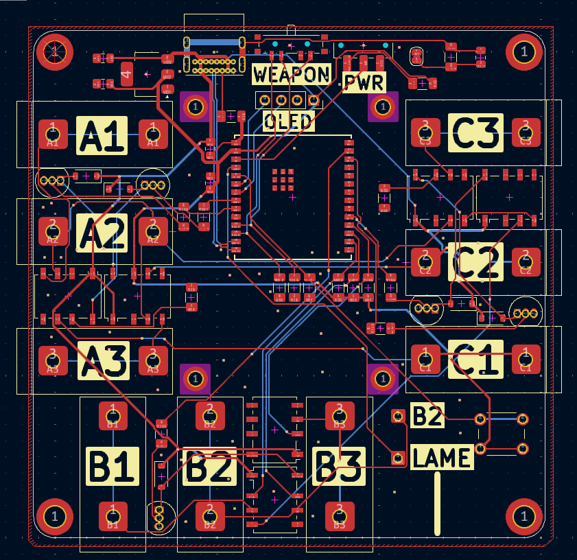
2 layers79 × 78.3 mmLogic testing, the printed circuit board in 3D

Fencing Tester is a tool for testing and analysing basic fencing equipment. It is intended for situations where you may not have access to a full piste setup to test equipment during repair or when you are tired of…

Size
79 × 78.3 mm
Copper layers
2
Thickness
1.6 mm
Parts
58
Nets
67
Pads
245
Tracks, vias
453, 110
Pours
1
Routed
Yes
KiCad
KiCad 9.0 (file 20241229)
Created
29 May 2025
Updated
25 Jul 2025

Overview

Logic testing is an open-source printed circuit board by josh-lambda, from the josh-lambda/fencing-tester repository on GitHub. It is a 2-layer board of 79 × 78.3 mm with 58 parts on 67 nets, routed with 453 tracks and 110 vias.

It is built around the AMS1117-3.3, ESP32-C6-WROOM-1U-N8 and BC547. Its parts include 16 resistors, 9 switches, 7 connectors, 5 capacitors and 5 diodes. It belongs with the ESP32 and RISC-V boards of this library.

Main components

3

README

README.md

Fencing Tester

Fencing Tester is a tool for testing and analysing basic fencing equipment. It is intended for situations where you may not have access to a full piste setup to test equipment during repair or when you are tired of manually jabbing a weapon button a hundred times while trying to find which part of a reel/cable set decided to break this time.

It aims to provide basic troubleshooting functionality including:

  • Weapon readout for Eppe, Foil & Sabre
  • Body wire resistance testing for Eppe, Foil, & Sabre
  • Test signal generator for troubleshooting pistes

Images
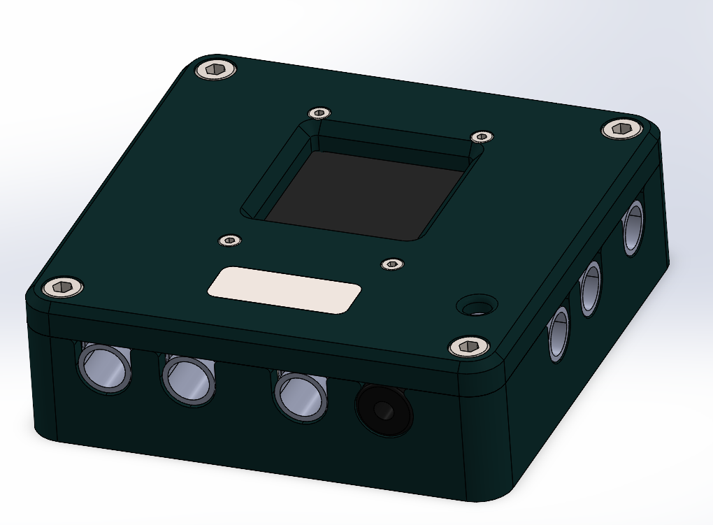
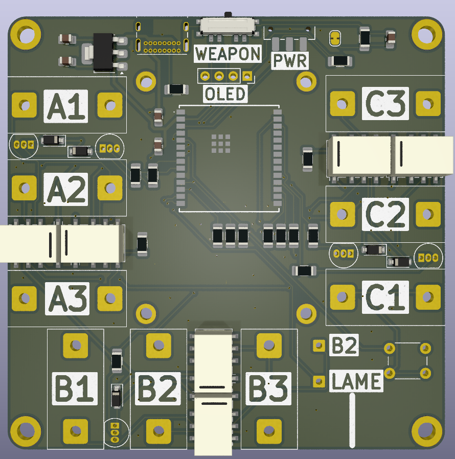
Completed Case Full PCB Full PCB render

Why did I make this?

I created this project due to an interest in the electrical signaling protocols used in fencing, and fascination with the reliable and intricate mechanisms that make modern blades work. This spiraled into creating a multi-function testing device with signal generation, weapon readout, and wire checking for fun.

BOM

See BOM.csv for full details

CATEGORYITEMQUANTITY
COMPONENTSG6K-2P-Y 5V6
1N41485
BC5476
10uF Capacitors2
0.1uF/100nF2
1nF Capacitors1
10k Resistor6
510 Resistor5
1 Resistor3
5.1k Resistor1
1M Resistor1
Display 128x128 I2C1
AMS1117-3.31
Banana Plugs9
3mm Plug1
USB-C Connector1
Pin Headers Female4
Push Button1
2P Switch1
3P Switch1
ESP32-C6-WROOM-1U1
HARDWAREM4x20 Socket Head4
M2x10 Socket head4
MATERIALSPLA 1kg1
3mm Sheet1

Parts

58
QtyValueFootprintReferences
610kCustom:R_1206_3216Metric_Pad1.30x1.75mm_HandSolder_TextR12, R13, R14, R15, R16, R17
6G6K-2Relay_SMD:Relay_DPDT_Omron_G6K-2F-YK1, K2, K3, K4, K5, K6
51N4148Diode_SMD:D_SOD-123D1, D2, D3, D4, D5
5510Custom:R_1206_3216Metric_Pad1.30x1.75mm_HandSolder_TextR1, R2, R3, R6, R8
5BC547Package_TO_SOT_THT:TO-92_InlineQ1, Q2, Q3, Q4, Q5
4MountingHoleMountingHole:MountingHole_3.2mm_M3_ISO7380_Pad_TopBottomH1, H2, H3, H4
4MountingHoleMountingHole:MountingHole_2.2mm_M2_DIN965_Pad_TopBottomH5, H6, H7, H8
31ΩCustom:R_1206_3216Metric_Pad1.30x1.75mm_HandSolder_TextR4, R5, R7
20.1 µFCapacitor_SMD:C_0805_2012Metric_Pad1.18x1.45mm_HandSolderC8, C9
210 µFCapacitor_SMD:C_0805_2012Metric_Pad1.18x1.45mm_HandSolderC6, C7
11 nFCapacitor_SMD:C_0805_2012Metric_Pad1.18x1.45mm_HandSolderC3
11MCustom:R_1206_3216Metric_Pad1.30x1.75mm_HandSolder_TextR11
15.1kCustom:R_1206_3216Metric_Pad1.30x1.75mm_HandSolder_TextR9
1AMS1117-3.3Package_TO_SOT_SMD:SOT-223U2
1Aux WireCustom:Fencing PlugJ2
1Conn_01x04Connector_PinSocket_2.54mm:PinSocket_1x04_P2.54mm_VerticalJ3
1ESP32-C6-WROOM-1U-N8Importer:ESP32C6WROOM1UN8IC1
1External BoxCustom:Fencing PlugJ1
1Lame TabConnector_Wire:SolderWire-0.5sqmm_1x01_D0.9mm_OD2.1mmJ4
1SW_DP3TButton_Switch_SMD:SW_SP3T_PCM13SW2
1SW_PushButton_Switch_THT:SW_PUSH_6mm_H13mmSW3
1SW_SPDTButton_Switch_SMD:SW_SPDT_CK_JS102011SAQNSW1
1Small PinConnector_Wire:SolderWire-0.5sqmm_1x01_D0.9mm_OD2.1mmJ6
1SolderJumper_2_ClosedJumper:SolderJumper-2_P1.3mm_Bridged_RoundedPad1.0x1.5mmJP1
1Test OutputCustom:Fencing PlugJ5
1USB_C_Plug_USB2.0Connector_USB:USB_C_Receptacle_GCT_USB4085P1

Questions

How big is the Logic testing PCB?

It measures 79 × 78.3 mm and has 2 copper layers, 1.6 mm thick.

What parts does the Logic testing use?

58 parts, built around the AMS1117-3.3, ESP32-C6-WROOM-1U-N8 and BC547. The full list of its parts is on this page, with links to each part's symbol and footprint where PCBKit's library has them.

Where can I download the Logic testing KiCad files?

From the josh-lambda/fencing-tester repository on GitHub, at the commit this page was made from: the board is PCB/Logic testing.kicad_pcb and its schematic PCB/Logic testing.kicad_sch. PCBKit opens the board in the browser, with nothing to install.

Can I use the Logic testing design in my own project?

Its repository states no licence, so its author keeps all rights: ask josh-lambda before reusing the design.

Similar boards

  • 2 layers80 × 107.5 mmMinino, the printed circuit board in 3D

    Minino

    ElectronicCats/Minino

    Minino is an original multiprotocol and multiband board made for sniffing, communicating, and attacking IoT devices. It was designed as a mini Cat that integrates the powerful ESP32C6, GPS, microSD and OLED.

    79 parts183GPL-3.0
  • 2 layers100 × 102 mmMpair, the printed circuit board in 3D

    Mpair

    marpi82/mpair

    Advanced Air Quality Monitoring Station based on ESP32's

    198 parts2
  • 2 layers100 × 80 mmBrewingstation3, the printed circuit board in 3D

    Brewingstation3

    Gr3yh0und/brewingstation

    Automate your brew day: ESP32 + induction cooktop + PID control, talking MQTT to CraftBeerPi.

    51 parts1MIT
  • 2 layers89.5 × 50 mmBSC finish punches transmitter, the printed circuit board in 3D

    BSC finish punches transmitter

    ut-ims-robotics/eensaar-thesis-2026-wireless-finish-punch-transmission

    This repository hosts the source code, electrical schematics and layout, as well as documentation developed by Emil Eensaar for his Bachelor of Science thesis.

    63 parts1Apache-2.0
  • 2 layers94.7 × 71.8 mmIoT Logger B 1.0, the printed circuit board in 3D

    IoT Logger B 1.0

    WestianPKl/pcb-docs

    A collection of custom PCB designs created in KiCAD, centered around the Raspberry Pi Pico (RP2040) platform. Each board is a standalone module that connects to the Main Board and extends its functionality via I2C, SPI…

    147 parts
  • 2 layersNavigatorschema, the printed circuit board in 3D

    Navigatorschema

    maddevsio/mad-navigator

    Mad navigator is simple compass-like device shows direction to predefined geo point. This repository contains firmware source code and schematics for device.

    107 parts14
  • 2 layers45.7 × 60.2 mmPcb watch, the printed circuit board in 3D

    Pcb watch

    nithinmathewjoji/Schrodinger-Clock-PCB-Watch-

    An open-source ESP32-S3-based smartwatch with RTC, I2C display, buzzer, LEDs, and battery monitoring. Designed using KiCad, it features a compact PCB layout, Li-Po battery support, and USB charging

    58 parts4MIT