4 layers119.8 × 129.8 mm

 jorisplusplus/pcdock
FPGA base pcdock
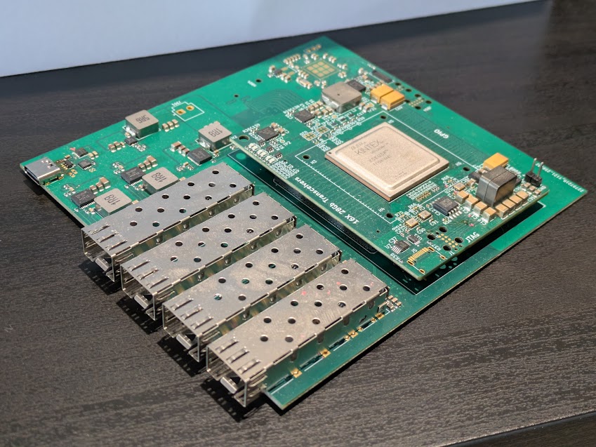
Base board is an open-source printed circuit board by jorisplusplus, from the jorisplusplus/pcdock repository on GitHub. It is a 6-layer board of 119.8 × 129.8 mm with 236 parts on 502 nets, routed with 4,947 tracks and 802 vias.
It is built around the TPS53318DQPR, TLV62569DBV and TPS56637RPAR, with the W25Q128JVSIQ, ESP32-P4 and ADM6-60-01.5-L-4-2-A-TR among its other parts. Its parts include 116 capacitors, 73 resistors, 15 connectors, 14 inductors and 9 ICs. It belongs with the ESP32 and RISC-V boards of this library.


The goal of this project is to make a device that can pipe displayport and USB 3 signals over a single 25 gbps fiber and provide kvm switch to switch between different sources.
For this project the Xilinx FPGA XCKU5P-2FFVB676I has been chosen. It has 16 transceivers capable of 25 gbps and is reasonably priced at around 80 euros. The hardware is broken up into various pieces, this is to reduce production costs by being able to reuse parts and reduce costs for prototyping if mistakes are made.
The hardware can be broken up into the following pieces:
Currently 3 working FPGA cards have been produced. And the fiber optic ports on the base board have been validated being capable of sending/receiving 25 gbps signals.
| Qty | Value | Footprint | References |
|---|---|---|---|
| 38 | 100nF | Capacitor_SMD:C_0603_1608Metric | C304, C314, C325, C335, C341, C501, C502, C505, C506, C801, C802, C805, C1001, C1002, C1005, C1006 +22 |
| 25 | 4.7k | Resistor_SMD:R_0402_1005Metric | R1, R2, R3, R4, R5, R6, R7, R8, R501, R502, R505, R801, R802, R1001, R1002, R1005 +9 |
| 16 | 100nF | Capacitor_SMD:C_0201_0603Metric | C507, C508, C509, C510, C807, C808, C809, C810, C907, C908, C909, C910, C1007, C1008, C1009, C1010 |
| 15 | 22uF | Capacitor_SMD:C_0805_2012Metric | C317, C318, C319, C320, C321, C322, C328, C329, C330, C338, C339, C340, C812, C813, C858 |
| 13 | 10k | Resistor_SMD:R_0402_1005Metric | R307, R316, R324, R325, R326, R327, R328, R332, R806, R807, R809, R816, R817 |
| 12 | 1uF | Capacitor_SMD:C_0603_1608Metric | C303, C313, C324, C608, C831, C832, C834, C836, C837, C911, C912, C913 |
| 11 | 10uF | Capacitor_SMD:C_0603_1608Metric | C503, C504, C611, C613, C803, C804, C833, C903, C904, C1003, C1004 |
| 8 | 10uF | Capacitor_SMD:C_0805_2012Metric | C302, C307, C308, C309, C310, C311, C331, C332 |
| 8 | L | Inductor_SMD:L_0805_2012Metric | L501, L502, L801, L802, L901, L902, L1001, L1002 |
| 6 | 0 | Resistor_SMD:R_0402_1005Metric | R808, R818, R819, R820, R904, R907 |
| 5 | 100k | Resistor_SMD:R_0402_1005Metric | R305, R309, R317, R803, R804 |
| 5 | 100nF | Capacitor_SMD:C_0402_1005Metric | C305, C316, C327, C914, C915 |
| 4 | MountingHole | MountingHole:MountingHole_2.2mm_M2 | H801, H802, H803, H804 |
| 4 | SFP+ | Connector:Connector_SFP_and_Cage | J501, J801, J901, J1001 |
| 3 | 1.8uH | Inductor_SMD:L_Changjiang_FXL0840 | L301, L302, L303 |
| 3 | 10 | Resistor_SMD:R_0402_1005Metric | R603, R607, R906 |
| 3 | 115k | Resistor_SMD:R_0402_1005Metric | R304, R313, R321 |
| 3 | 1k | Resistor_SMD:R_0402_1005Metric | R301, R312, R320 |
| 3 | 1nF | Capacitor_SMD:C_0402_1005Metric | C306, C315, C326 |
| 3 | 4.7uF | Capacitor_SMD:C_1206_3216Metric | C301, C312, C323 |
| 3 | 820k | Resistor_SMD:R_0402_1005Metric | R302, R310, R318 |
| 3 | 82k | Resistor_SMD:R_0402_1005Metric | R303, R311, R319 |
| 3 | Conn_02x30_Odd_Even | libs:HRS_ER8-60S-0.8SV-5H | J401, J402, J404 |
| 3 | TPS53318DQPR | libs:CONV_TPS53318DQPR | U301, U302, U303 |
| 2 | 22pF | Capacitor_SMD:C_0603_1608Metric | C820, C821 |
| 2 | 330pF | Capacitor_SMD:C_0603_1608Metric | C607, C610 |
| 2 | TestPoint | TestPoint:TestPoint_Pad_D2.0mm | TP801, TP802 |
| 1 | 100pF | Capacitor_SMD:C_0402_1005Metric | C336 |
| 1 | 19.1k | Resistor_SMD:R_0402_1005Metric | R323 |
| 1 | 191k | Resistor_SMD:R_0402_1005Metric | R331 |
| 1 | 2.2uH | Inductor_SMD:L_Changjiang_FXL0412 | L803 |
| 1 | 22uH | Inductor_SMD:L_1210_3225Metric | L903 |
| 1 | 4.02k | Resistor_SMD:R_0402_1005Metric | R810 |
| 1 | 40MHz | Crystal:Crystal_SMD_3225-4Pin_3.2x2.5mm | Y801 |
| 1 | 430 | Resistor_SMD:R_0402_1005Metric | R322 |
| 1 | 44.2k | Resistor_SMD:R_0402_1005Metric | R315 |
| 1 | 5.6uH | Inductor_SMD:L_Changjiang_FXL0840 | L304 |
| 1 | 69.8k | Resistor_SMD:R_0402_1005Metric | R306 |
| 1 | 750 | Resistor_SMD:R_0402_1005Metric | R314 |
| 1 | 820 | Resistor_SMD:R_0402_1005Metric | R308 |
| 1 | ADM6-60-01.5-L-4-2-A-TR | libs:SAMTEC_ADM6-60-01.5-L-4-2-A-TR_GPIO | J701 |
| 1 | ADM6-60-01.5-L-4-2-A-TR | libs:SAMTEC_ADM6-60-01.5-L-4-2-A-TR_TRANS | J703 |
| 1 | AP3019A | Package_TO_SOT_SMD:TSOT-23-6 | U901 |
| 1 | AP90P03Q | Package_SON:Diodes_PowerDI3333-8 | Q601 |
| 1 | Conn_01x02 | Connector_JST:JST_VH_B2P-VH-B_1x02_P3.96mm_Vertical | J301 |
| 1 | Conn_01x03 | Connector_PinHeader_2.54mm:PinHeader_1x03_P2.54mm_Vertical | J803 |
| 1 | Conn_02x15_Counter_Clockwise | footprints:YXT-BB10-30S-02 | J902 |
| 1 | ESP32-P4 | PCM_Espressif:ESP32-P4 | U803 |
| 1 | HUSB238 | Package_DFN_QFN:DFN-10-1EP_3x3mm_P0.5mm_EP1.7x2.5mm | U601 |
| 1 | JTAG | Connector:Tag-Connect_TC2050-IDC-FP_2x05_P1.27mm_Vertical | J802 |
| 1 | SP0504BAHT | Package_TO_SOT_SMD:SOT-23-5 | D301 |
| 1 | TLV62569DBV | Package_TO_SOT_SMD:SOT-23-5 | U801 |
| 1 | TPS56637RPAR | libs:CONV_TPS56637RPAR | U305 |
| 1 | UART | Connector:Tag-Connect_TC2050-IDC-FP_2x05_P1.27mm_Vertical | J804 |
| 1 | USB_C_Receptacle_USB2.0 | Connector_USB:USB_C_Receptacle_HRO_TYPE-C-31-M-12 | J601 |
| 1 | W25Q128JVS | Package_SO:SOIC-8_5.23x5.23mm_P1.27mm | U802 |
| 1 | xxx | Resistor_SMD:R_0402_1005Metric | R605 |
It measures 119.8 × 129.8 mm and has 6 copper layers, 1.6 mm thick.
236 parts, built around the TPS53318DQPR, TLV62569DBV, TPS56637RPAR and W25Q128JVSIQ. The full list of its parts is on this page, with links to each part's symbol and footprint where PCBKit's library has them.
From the jorisplusplus/pcdock repository on GitHub, at the commit this page was made from: the board is base_board/base_board.kicad_pcb and its schematic base_board/USB.kicad_sch. PCBKit opens the board in the browser, with nothing to install.
Its repository states no licence, so its author keeps all rights: ask jorisplusplus before reusing the design.


TobleMiner/blinkekatze-charger
A USB-C powered 20 port 5V 1.5A USB-C charger

Biswajitpattanaik07/6_Axis_Robot_Controller
Axion is an open-source controller board for a 6-axis articulated robot arm. It is built around an STM32F103C8T6 and combines six servo outputs, six per-joint IMU inputs, and three ways to talk to the outside world…

