Skip to the content
2 layers154.8 × 112.3 mmGNS530, the printed circuit board in 3D

A DIY Garmin GNS 530-inspired panel for flight simulation, powered by MobiFlight.

Size
154.8 × 112.3 mm
Copper layers
2
Thickness
1.6 mm
Parts
81
Nets
102
Pads
293
Tracks, vias
257, 3
Pours
1
Routed
Yes
KiCad
KiCad 9.0 (file 20241229)
Created
15 Aug 2026
Updated
20 Sep 2026

Overview

GNS530 is an open-source printed circuit board by JorgHendriks, from the JorgHendriks/mobiflight-gns530 repository on GitHub. It is a 2-layer board of 154.8 × 112.3 mm with 81 parts on 102 nets, routed with 257 tracks and 3 vias.

It is built around the 74HC165D, PEC11D-4120F-S0015 and AO3401A, with the BC847 among its other parts. Its parts include 38 resistors, 14 diodes, 2 transistors, 1 capacitor and 1 IC. It belongs with the RP2040 boards of this library.

Main components

4

README

pcb/README.md

PCB

PCB manufacturing

The ready-to-order fabrication archive is GNS530_v1_1_pcb_fab.zip. Use a standard board thickness of 1.6 mm.

The local symbol and footprint libraries are referenced through ${KIPRJMOD}.

Bill of materials

DesignatorsQtyComponentSpecification
RE_GPS1, RE_COM_VLOC12Dual-concentric encoderPEC11D-4120F-S0015
Q21P-channel MOSFETAO3401A, SOT-23
C11Capacitor0.1 uF, 1206
R1-R23, R32-R3628Resistor220 ohm, 1206
R24-R31, R39, R4010Resistor10 kohm, 1206
Q11NPN transistorBC847, SOT-23
SW_CDI1, SW_CLR1, SW_COM1, SW_DCT1, SW_ENT1, SW_FPL1, SW_MENU1, SW_MSG1, SW_OBS1, SW_PROC1, SW_RNG_D1, SW_RNG_UP1, SW_V1, SW_VNAV114Illuminated tactile switch6 x 6 x 7.2 mm, six pins
D1-D1414LED3 mm clear through-hole
U11Shift register74HC165, SOIC-16
RE_VOL_COM1, RE_VOL_V12Rotary encoder with switchPEC11L-4220F-S0015
EXT_LED11Two-pin header2.54 mm pitch
A11MicrocontrollerRaspberry Pi Pico
-2Male pin header20 pins, 2.54 mm pitch
-2Female socket header20 pins, 2.54 mm pitch

Illuminated switches

Use 6 x 6 x 7.2 mm, six-pin illuminated tactile switches. Four pins form the duplicated switch contacts; the remaining two connect the LED.
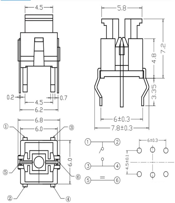
Illuminated tactile switch dimensions

The small square PCB pad is ground and connects to the negative LED terminal.

Display

The enclosure is designed for a PCB800099 HDMI/VGA/AV controller and ZJ050NA-08C 5-inch 640 x 480 LCD.
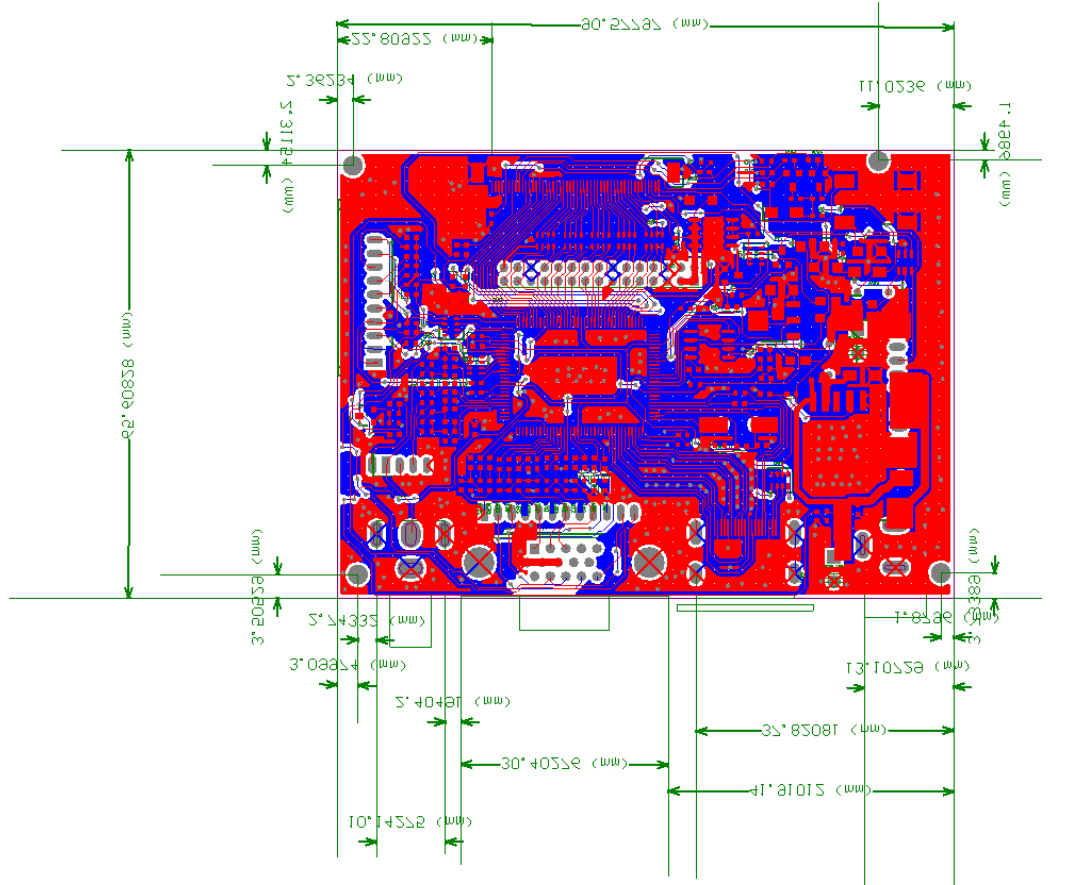
PCB800099 controller

PartSpecification
PCB800099 controller100 x 55 x 10 mm; 12 V DC, more than 1 A
ZJ050NA-08C LCD117.65 x 88.43 x 5.9 mm; 50-pin parallel RGB

The display controller uses its own 12 V supply. Do not connect 12 V to the Pico or the LCD panel input.

If your controller board includes VGA and composite-video connectors, desolder them before assembly. Alternatively, modify the back cover to provide adequate clearance for the connectors.

Parts

81
QtyValueFootprintReferences
28220Resistor_SMD:R_1206_3216MetricR1, R2, R10, R11, R12, R13, R14, R15, R16, R17, R18, R19, R20, R21, R22, R23 +12
14LEDLED_THT:LED_D3.0mm_ClearD1, D2, D3, D4, D5, D6, D7, D8, D9, D10, D11, D12, D13, D14
14SW_Push_LED_6pAvionics:SW_PUSH_LED_6mm_H7.2mmSW_CDI1, SW_CLR1, SW_COM1, SW_DCT1, SW_ENT1, SW_FPL1, SW_MENU1, SW_MSG1, SW_OBS1, SW_PROC1, SW_RNG_D1, SW_RNG_UP1, SW_V1, SW_VNAV1
1010kResistor_SMD:R_1206_3216MetricR24, R25, R26, R27, R28, R29, R30, R31, R39, R40
5MountingHoleMountingHole:MountingHole_2.2mm_M2H1, H2, H3, H4, H5
2PEC11D-4120F-S0015Avionics:PEC11D4120FS0015RE_COM_VLOC1, RE_GPS1
2RotaryEncoder_SwitchAvionics:RotaryEncoder_Alps_EC11E-Switch_Vertical_H20mmRE_VOL_COM1, RE_VOL_V1
10.1uResistor_SMD:R_1206_3216MetricC1
174HC165Package_SO:JEITA_SOIC-16_3.9x9.9mm_P1.27mmU1
1AO3401APackage_TO_SOT_SMD:SOT-23Q2
1BC847Package_TO_SOT_SMD:SOT-23Q1
1RaspberryPi_PicoAvionics:RaspberryPi_Pico_Common_UnspecifiedA1
1TestPoint_2PoleConnector_PinHeader_2.54mm:PinHeader_2x01_P2.54mm_VerticalEXT_LED1

Similar boards

  • 4 layers29.3 × 187.1 mmLeft Frame, the printed circuit board in 3D

    Left Frame

    FlightDeckDIY/G1000-NXi-Mega

    Welcome to the G1000 NXi Mega project! This repository contains the schematic and PCB design files for a custom-built G1000 avionics panel, designed specifically for use with flight simulators like Microsoft Flight…

    127 parts14
  • 2 layers75 × 55.4 mmGaiaBeronia, the printed circuit board in 3D

    GaiaBeronia

    dihermos/GaiaBeronia

    Gaia Beronia is an inspired on Flipper Zero embeeded system. It uses a system based on Python running on Linux in a Raspberry Pi Zero 2W.

    31 parts1Apache-2.0
  • 4 layers350 × 350 mmInputSystem original, the printed circuit board in 3D

    InputSystem original

    ETM-Code/Tarski-Schematics

    KiCad schematics and PCB layouts for Project Tarski's analogue neuromorphic accelerator

    3,443 partsApache-2.0
  • 2 layers151 × 95 mmDeneme, the printed circuit board in 3D

    Deneme

    g210101021/OpenStylophone-RP2040

    Overview • Technical Summary • Architecture • Hardware Audit & Remediation • Schematic Subsystems • PCB Layout • Firmware Roadmap • Bill of Materials • Author

    143 parts
  • 2 layers50 × 35 mmController module, the printed circuit board in 3D

    Controller module

    InputBlackBoxOutput/INGAME

    Virtual reality controller for playing FPS games

    73 partsMIT
  • 4 layers240 × 180 mmOparroy ci, the printed circuit board in 3D

    Oparroy ci

    kristofferkoch/oparroy

    WS2812 inspired versatile serial protocol and hardware

    570 partsMIT
  • 2 layers191.5 × 116 mmPiDaughterBoard, the printed circuit board in 3D

    PiDaughterBoard

    mekatrol/electronics

    This repository contains the electronics, embedded firmware, support software, and reference material for a collection of home-automation and workshop projects.

    175 parts

Questions

How big is the GNS530 PCB?

It measures 154.8 × 112.3 mm and has 2 copper layers, 1.6 mm thick.

What parts does the GNS530 use?

81 parts, built around the 74HC165D, PEC11D-4120F-S0015, AO3401A and BC847. The full list of its parts is on this page, with links to each part's symbol and footprint where PCBKit's library has them.

Where can I download the GNS530 KiCad files?

From the JorgHendriks/mobiflight-gns530 repository on GitHub, at the commit this page was made from: the board is pcb/GNS530.kicad_pcb and its schematic pcb/GNS530.kicad_sch. PCBKit opens the board in the browser, with nothing to install.

Can I use the GNS530 design in my own project?

Its repository states no licence, so its author keeps all rights: ask JorgHendriks before reusing the design.