4 layers133.9 × 165.1 mm
Main VCO board
JordanAceto/micro_ox
Monosynth with analog signal path and digital controls. SSI2130 VCOs and SSI2140 VCF.
295 parts8CC-BY-4.0

 JordanAceto/Phasor_II6
6-stage optical phase shifter pedal ala the Mu-tron II with extra features
Phasor II is an open-source printed circuit board by JordanAceto, from the JordanAceto/Phasor_II repository on GitHub, published under the CC-BY-4.0 licence. It is a 2-layer board of 84.5 × 108.3 mm with 196 parts on 105 nets, routed with 1,230 tracks and 151 vias.
It is built around the RC4558D, TL072 and B5819W, with the 1N4148W, BAT48ZFILM and MMBT3906 among its other parts. Its parts include 77 resistors, 55 capacitors, 10 ICs, 9 diodes and 4 connectors. It belongs with the audio and music boards of this library.


RATE, DEPTH, and FEEDBACK controlsLFO DEPTHLFO RATEMANUAL SWEEP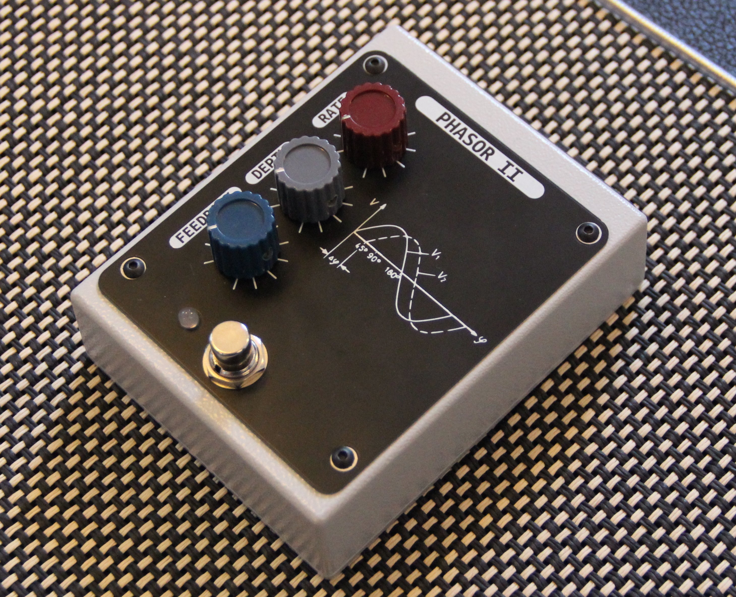
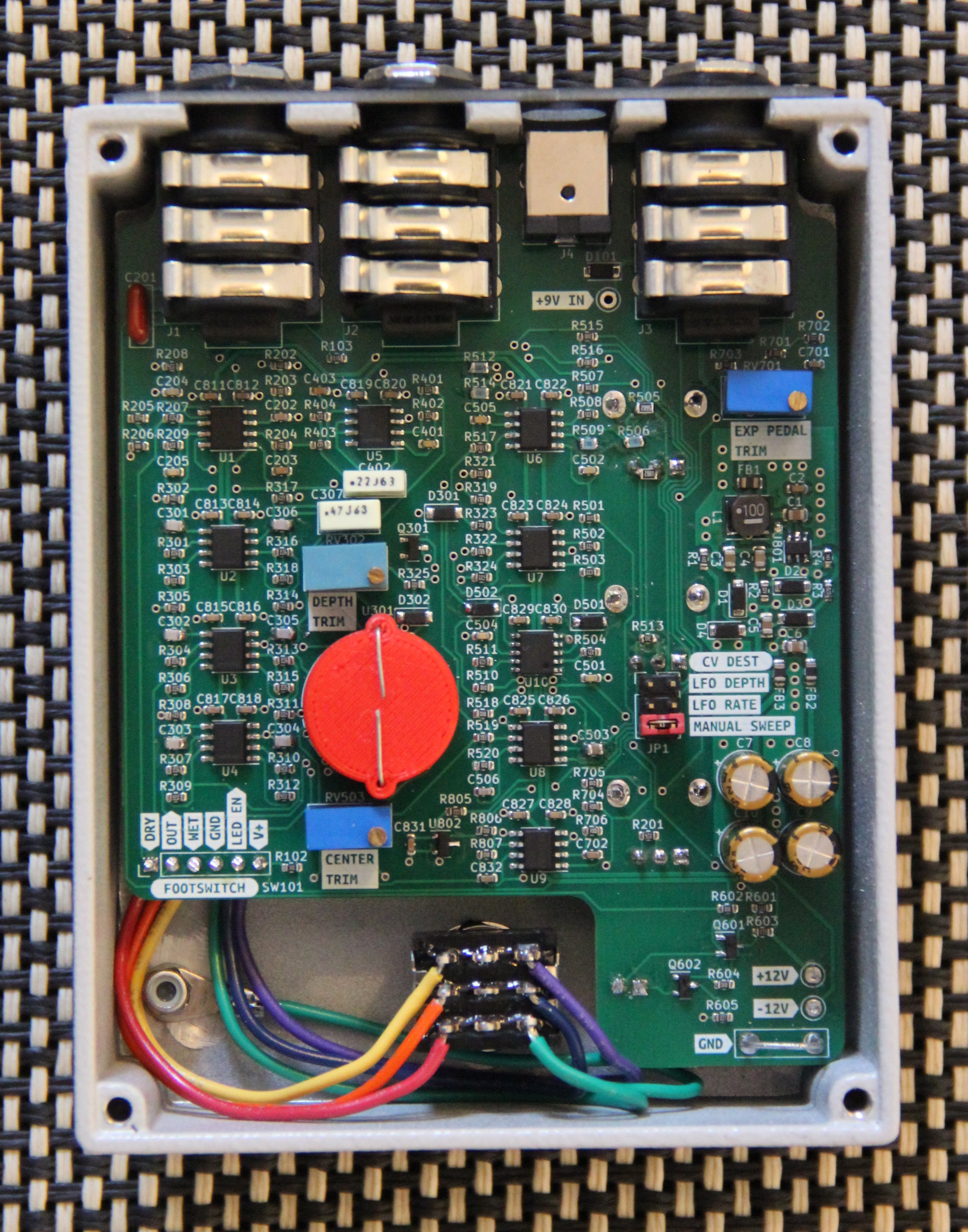
EXP PEDAL TRIM
CV-PED jack and power the pedal ONCV-PED jack relative to ground (there is a convenient place to clip the black lead of the multimeter on the pcb)EXP PEDAL TRIM trimpot until you measure +5VDCCV-PED jack sweeps from 0v to +5vDEPTH TRIM
CENTER TRIM
The depth and center trims are somewhat interactive, and should be trimmed together iteratively. Try a variety of rate and depth settings while calibrating.
Note that while there is a light shield covering the photocells, ambient light will slightly change the sweep when the back panel is off
| Task | Status |
|---|---|
| Schematic capture | ☑ |
| PCB layout | ☑ |
| Test build | ☑ |
| Safe to order boards | ☑ |
| Qty | Value | Footprint | References |
|---|---|---|---|
| 26 | 100n | Capacitor_SMD:C_0603_1608Metric | C2, C203, C701, C702, C811, C812, C813, C814, C815, C816, C817, C818, C819, C820, C821, C822 +10 |
| 20 | 4k7 | Resistor_SMD:R_0603_1608Metric | R201, R205, R207, R208, R209, R301, R303, R304, R306, R307, R309, R310, R312, R313, R315, R316 +4 |
| 11 | 100k | Resistor_SMD:R_0603_1608Metric | R501, R507, R510, R515, R518, R520, R602, R604, R705, R806, R807 |
| 8 | 220k | Resistor_SMD:R_0603_1608Metric | R302, R305, R308, R311, R314, R317, R324, R502 |
| 6 | 1n | Capacitor_SMD:C_0603_1608Metric | C205, C401, C501, C502, C504, C505 |
| 6 | 6n8 | Capacitor_SMD:C_0805_2012Metric | C301, C302, C303, C304, C305, C306 |
| 5 | 10k | Resistor_SMD:R_0603_1608Metric | R102, R323, R513, R701, R702 |
| 5 | B5819W | Diode_SMD:D_SOD-123 | D1, D2, D3, D4, D101 |
| 5 | RC4558 | Package_SO:SOIC-8_3.9x4.9mm_P1.27mm | U1, U2, U3, U4, U5 |
| 4 | 10u | Capacitor_THT:CP_Radial_D6.3mm_P2.50mm | C7, C8, C9, C10 |
| 4 | TL072 | Package_SO:SOIC-8_3.9x4.9mm_P1.27mm | U6, U7, U8, U9 |
| 3 | 100R @ 100MHz | Inductor_SMD:L_0805_2012Metric | FB1, FB2, FB3 |
| 3 | 270 | Resistor_SMD:R_0603_1608Metric | R504, R511, R605 |
| 3 | 4u7 | Capacitor_SMD:C_0805_2012Metric | C1, C5, C6 |
| 2 | 1 | Resistor_SMD:R_0603_1608Metric | R1, R2 |
| 2 | 100k | Potentiometer_THT:Potentiometer_Bourns_3296W_Vertical | RV503, RV701 |
| 2 | 100k | custom_footprints:Potentiometer_Alpha_RD901F-40-00D_Single_Vertical | RV501, RV502 |
| 2 | 120k | Resistor_SMD:R_0603_1608Metric | R512, R514 |
| 2 | 12k | Resistor_SMD:R_0603_1608Metric | R403, R508 |
| 2 | 1N4148W | Diode_SMD:D_SOD-123 | D301, D302 |
| 2 | 1u | Capacitor_SMD:C_0805_2012Metric | C3, C4 |
| 2 | 200k | Resistor_SMD:R_0603_1608Metric | R704, R706 |
| 2 | 22k | Resistor_SMD:R_0603_1608Metric | R503, R603 |
| 2 | 390k | Resistor_SMD:R_0603_1608Metric | R202, R204 |
| 2 | 3k9 | Resistor_SMD:R_0603_1608Metric | R203, R321 |
| 2 | 56k | Resistor_SMD:R_0603_1608Metric | R505, R517 |
| 2 | 68k | Resistor_SMD:R_0603_1608Metric | R319, R322 |
| 2 | BAT48ZFILM | Diode_SMD:D_SOD-123 | D501, D502 |
| 2 | MMBT3906 | Package_TO_SOT_SMD:SOT-23 | Q601, Q602 |
| 1 | +12 | TestPoint:TestPoint_Keystone_5000-5004_Miniature | TP804 |
| 1 | +9 | TestPoint:TestPoint_Keystone_5000-5004_Miniature | TP802 |
| 1 | -12 | TestPoint:TestPoint_Keystone_5000-5004_Miniature | TP803 |
| 1 | 100p | Capacitor_SMD:C_0603_1608Metric | C506 |
| 1 | 10k | custom_footprints:Potentiometer_Alpha_RD901F-40-00D_Single_Vertical | RV201 |
| 1 | 10uH, 1.2A | Inductor_SMD:L_Taiyo-Yuden_NR-50xx | L1 |
| 1 | 110k | Resistor_SMD:R_0603_1608Metric | R506 |
| 1 | 114k | Resistor_SMD:R_0603_1608Metric | R3 |
| 1 | 13k3 | Resistor_SMD:R_0603_1608Metric | R4 |
| 1 | 18k | Resistor_SMD:R_0603_1608Metric | R516 |
| 1 | 1k | Potentiometer_THT:Potentiometer_Bourns_3296W_Vertical | RV302 |
| 1 | 1k | Resistor_SMD:R_0603_1608Metric | R103 |
| 1 | 1k5 | Resistor_SMD:R_0603_1608Metric | R206 |
| 1 | 1k8 | Resistor_SMD:R_0603_1608Metric | R805 |
| 1 | 20k | Resistor_SMD:R_0603_1608Metric | R703 |
| 1 | 220 | Resistor_SMD:R_0603_1608Metric | R325 |
| 1 | 220n | Capacitor_THT:C_Rect_L7.0mm_W2.5mm_P5.00mm | C402 |
| 1 | 22p | Capacitor_SMD:C_0603_1608Metric | C202 |
| 1 | 30k | Resistor_SMD:R_0603_1608Metric | R509 |
| 1 | 33k | Resistor_SMD:R_0603_1608Metric | R601 |
| 1 | 39k | Resistor_SMD:R_0603_1608Metric | R519 |
| 1 | 3n3 | Capacitor_SMD:C_0603_1608Metric | C204 |
| 1 | 470n | Capacitor_THT:C_Rect_L7.0mm_W3.5mm_P5.00mm | C307 |
| 1 | 470p | Capacitor_SMD:C_0603_1608Metric | C403 |
| 1 | 47n | Capacitor_SMD:C_0805_2012Metric | C503 |
| 1 | 47n | Capacitor_THT:C_Rect_L7.0mm_W2.5mm_P5.00mm | C201 |
| 1 | 9VDC_IN | Connector_BarrelJack:BarrelJack_CUI_PJ-063AH_Horizontal | J4 |
| 1 | AUDIO_IN | custom_footprints:Jack_6.35mm_Neutrik_NMJ6HCD2_Horizontal | J1 |
| 1 | AUDIO_OUT | custom_footprints:Jack_6.35mm_Neutrik_NMJ6HCD2_Horizontal | J2 |
| 1 | EXP_PEDAL_CV_IN | custom_footprints:Jack_6.35mm_Neutrik_NMJ6HCD2_Horizontal | J3 |
| 1 | FOOTSWITCH | Connector_PinHeader_2.54mm:PinHeader_1x06_P2.54mm_Vertical | SW101 |
| 1 | G*** | kibuzzard-634AF413 | kibuzzard-634AF413 |
| 1 | G*** | kibuzzard-634AF403 | kibuzzard-634AF403 |
| 1 | G*** | kibuzzard-634AF397 | kibuzzard-634AF397 |
| 1 | G*** | kibuzzard-634B0BDD | kibuzzard-634B0BDD |
| 1 | G*** | kibuzzard-634B0C2B | kibuzzard-634B0C2B |
| 1 | G*** | kibuzzard-634B411E | kibuzzard-634B411E |
| 1 | G*** | kibuzzard-634AF3EB | kibuzzard-634AF3EB |
| 1 | G*** | kibuzzard-634AF4C9 | kibuzzard-634AF4C9 |
| 1 | G*** | kibuzzard-634B3AE3 | kibuzzard-634B3AE3 |
| 1 | G*** | kibuzzard-634AF4C0 | kibuzzard-634AF4C0 |
| 1 | G*** | kibuzzard-634AF45B | kibuzzard-634AF45B |
| 1 | G*** | kibuzzard-634AF436 | kibuzzard-634AF436 |
| 1 | G*** | kibuzzard-634AF49E | kibuzzard-634AF49E |
| 1 | G*** | kibuzzard-634B0B87 | kibuzzard-634B0B87 |
| 1 | G*** | kibuzzard-634AF448 | kibuzzard-634AF448 |
| 1 | G*** | kibuzzard-634AF4D7 | kibuzzard-634AF4D7 |
| 1 | G*** | kibuzzard-634B0BBC | kibuzzard-634B0BBC |
| 1 | G*** | kibuzzard-634AF3B0 | kibuzzard-634AF3B0 |
| 1 | GND | TestPoint:TestPoint_Bridge_Pitch7.62mm_Drill1.3mm | TP801 |
| 1 | LDR_ring | custom_footprints:LDR_ring | U301 |
The 190 most common of 196 parts.
It measures 84.5 × 108.3 mm and has 2 copper layers, 1.6 mm thick.
196 parts, built around the RC4558D, TL072, B5819W and 1N4148W. The full list of its parts is on this page, with links to each part's symbol and footprint where PCBKit's library has them.
From the JordanAceto/Phasor_II repository on GitHub, at the commit this page was made from: the board is main_pcb/kicad_6/phasor_II.kicad_pcb and its schematic jack_panel/kicad_6/phasor_II_jack_panel.kicad_sch. PCBKit opens the board in the browser, with nothing to install.
Its repository publishes it under the CC-BY-4.0 licence: you may reuse it on that licence's terms (keep the author's notice, and for a copyleft licence share your changes alike).
JordanAceto/micro_ox
Monosynth with analog signal path and digital controls. SSI2130 VCOs and SSI2140 VCF.

JordanAceto/VCF_plug_in_boards
Various small synthesizer Voltage Controlled Filter pcbs


sdylewski/Analog-Redial
A circuit board for old telephones to come back to life. Plug one or two phones in, and you can call the other phone, use bluetooth, connect to others via voip, and do a variety of other things with a plain old rotary…


Thorinair/Avalon-Harmonics
A collection of Avalon Harmonics branded synthesizer modules.

JordanAceto/modulation_source
Eurorack compatible pcb with sine/square VCLFO, white and pink noise, and sample & hold

powsplatboom/Synth-DIY
Where I will be collecting documentation for all my synth parts