

2 layers300 × 105 mm

 Joni0131/rospCar1
This repository contains the whole redevelopment of an old RC car. With the goal of changing the control system to an esp32 and a ROS communication with the computer to potentially implement a SLAM algorithm
UpgradePlan is an open-source printed circuit board by Joni0131, from the Joni0131/rospCar repository on GitHub. It is a 2-layer board of 120 × 110 mm with 31 parts on 68 nets, routed with 291 tracks and 4 vias.
It is built around the L293D and C945. Its parts include 14 resistors, 5 ICs, 3 transistors, 3 connectors and 2 diodes. It belongs with the ESP32 boards of this library.
This repository contains the whole redevelopment of an old RC car.
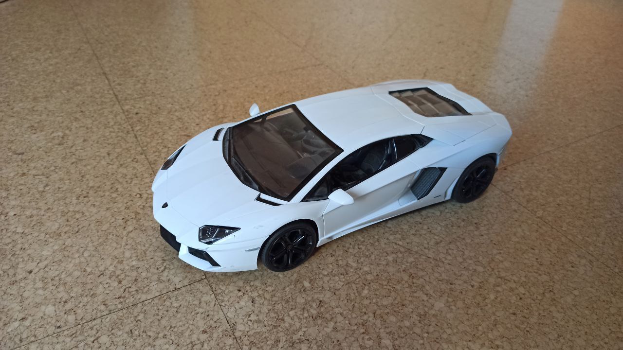 To change the control system to an esp32 and a ROS communication with the computer to potentially implement a SLAM algorithm.
I structured my work in the following four steps. Those are shortly discussed on this page for more detailed information on each step please correspond to each designated page.
The first step of the redevelopment process consists of understanding and checking the currently used electronics. As well as their functionality.
In the second phase, I chose the requirements for the new car, ordered parts that fulfill those requirements as well as designed the new circuit diagram.
The third step is considered the heart of the hardware development process. Here I define the functional requirements for the esp-32 and implement those decently.
Last but not least I design the other side of the communication and control algorithm for this project on the computer. The computer software is calculating the movements of the car and is using the sensor data to do this. Furthermore, it will be using a SLAM algorithm to map the whole area and it will be possible to go to certain locations easily.
| Qty | Value | Footprint | References |
|---|---|---|---|
| 3 | C945 | Package_TO_SOT_THT:TO-92 | Q1, Q2, Q4 |
| 2 | 120 | Resistor_THT:R_Axial_DIN0207_L6.3mm_D2.5mm_P15.24mm_Horizontal | R8, R13 |
| 2 | 1k | Resistor_THT:R_Axial_DIN0207_L6.3mm_D2.5mm_P15.24mm_Horizontal | R5, R6 |
| 2 | 220 | Resistor_THT:R_Axial_DIN0207_L6.3mm_D2.5mm_P15.24mm_Horizontal | R3, R4 |
| 2 | 3k | Resistor_THT:R_Axial_DIN0207_L6.3mm_D2.5mm_P15.24mm_Horizontal | R2, R11 |
| 2 | 4k7 | Resistor_THT:R_Axial_DIN0207_L6.3mm_D2.5mm_P15.24mm_Horizontal | R9, R10 |
| 2 | LED | Connector_Phoenix_SPT:PhoenixContact_SPT_2.5_2-V-5.0-EX_1x02_P5.0mm_Vertical | D1, D3 |
| 2 | LM350_TO220 | Package_TO_SOT_THT:TO-220-3_Horizontal_TabDown | U3, U4 |
| 1 | 100k | Resistor_THT:R_Axial_DIN0207_L6.3mm_D2.5mm_P15.24mm_Horizontal | R12 |
| 1 | 39 | Resistor_THT:R_Axial_DIN0207_L6.3mm_D2.5mm_P15.24mm_Horizontal | R7 |
| 1 | 390 | Resistor_THT:R_Axial_DIN0207_L6.3mm_D2.5mm_P15.24mm_Horizontal | R1 |
| 1 | 510 | Resistor_THT:R_Axial_DIN0207_L6.3mm_D2.5mm_P15.24mm_Horizontal | R14 |
| 1 | Battery_Cell | Connector_AMASS:AMASS_XT60-M_1x02_P7.20mm_Vertical | BT1 |
| 1 | Conn_HC_SR04 | Connector_PinHeader_2.54mm:PinHeader_1x04_P2.54mm_Horizontal | J3 |
| 1 | Conn_VL53L0/1xV2 | Connector_PinHeader_2.54mm:PinHeader_1x06_P2.54mm_Horizontal | J2 |
| 1 | Connector_GY_521 | MyESPConnector:GY-521 | J1 |
| 1 | Freenove-SP32-WROVER | MyESPConnector:MyESPConnector | U1 |
| 1 | L293D | Package_DIP:DIP-16_W7.62mm | U2 |
| 1 | LM317_TO-220 | Package_TO_SOT_THT:TO-220-3_Horizontal_TabDown | U5 |
| 1 | Motor_DC | Connector_Phoenix_SPT:PhoenixContact_SPT_2.5_2-V-5.0-EX_1x02_P5.0mm_Vertical | M1 |
| 1 | Motor_Servo | Connector_PinHeader_2.54mm:PinHeader_1x03_P2.54mm_Horizontal | M2 |
| 1 | SW_DPDT_x2 | Button_Switch_THT:SW_Slide_1P2T_CK_OS102011MS2Q | SW2 |
It measures 120 × 110 mm and has 2 copper layers, 1.6 mm thick.
31 parts, built around the L293D and C945. The full list of its parts is on this page, with links to each part's symbol and footprint where PCBKit's library has them.
From the Joni0131/rospCar repository on GitHub, at the commit this page was made from: the board is upgradePlan/circuit/circuit.kicad_pcb and its schematic oldSystem/initialSystem/initialSystem.kicad_sch. PCBKit opens the board in the browser, with nothing to install.
Its repository states no licence, so its author keeps all rights: ask Joni0131 before reusing the design.


fredsa/apple-color-monitor-iie-a2m2056
Apple ColorMonitor IIe (A2M2056) KiCad schematic


Starman3787/flightSimBuildB738
Project to build parts of a flight simulator for a Boeing 737-800

robinsonmourao/Esquema-eletrico-e-pcb-amplificador-classe-ab-duplo-par-diferencial
