2 layers21 × 49.5 mm
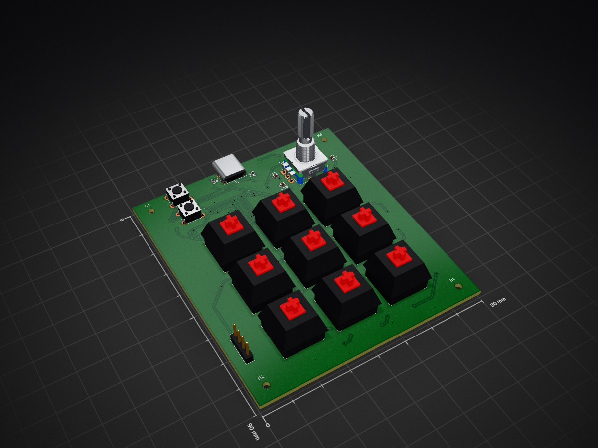
 johnppilli/macro-keypad
Custom USB-C mechanical macro keypad - KiCad PCB design around an RP2040
Macro keypad is an open-source printed circuit board by johnppilli, from the johnppilli/macro-keypad repository on GitHub. It is a 2-layer board of 80 × 90 mm with 70 parts on 68 nets, routed with 845 tracks and 112 vias.
It is built around the RP2040, W25Q16JVSSIQ and AP2112K-3.3, with the WS2812B among its other parts. Its parts include 27 capacitors, 18 diodes, 12 switches, 3 resistors and 3 ICs. It belongs with the keyboards and input boards and the RP2040 boards of this library.


A 3×3 hot-swap USB-C macro keypad built around an RP2040, with per-key RGB and a rotary encoder. Designed in KiCad from schematic through fabrication.
| Top | Bottom |
|---|---|
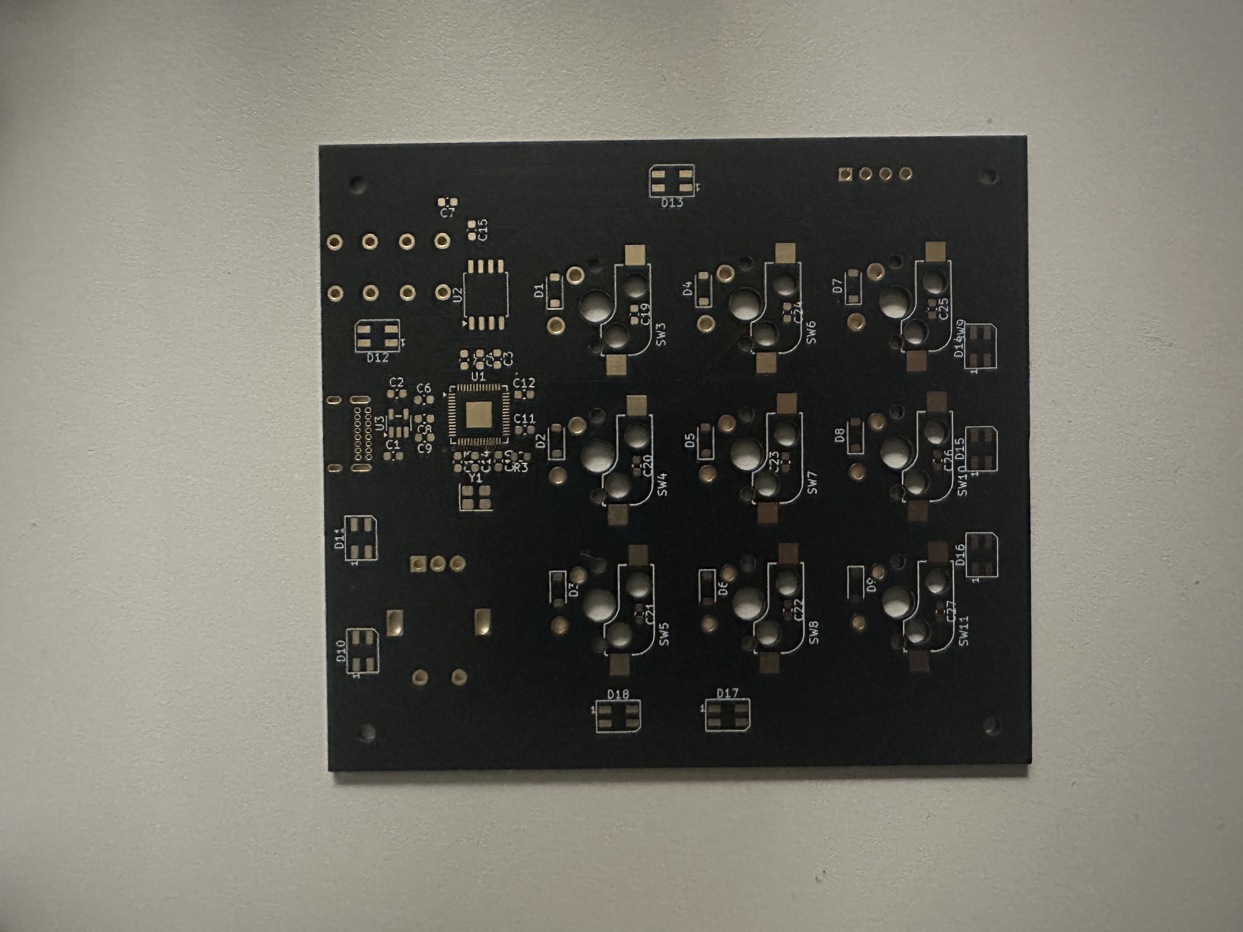 | 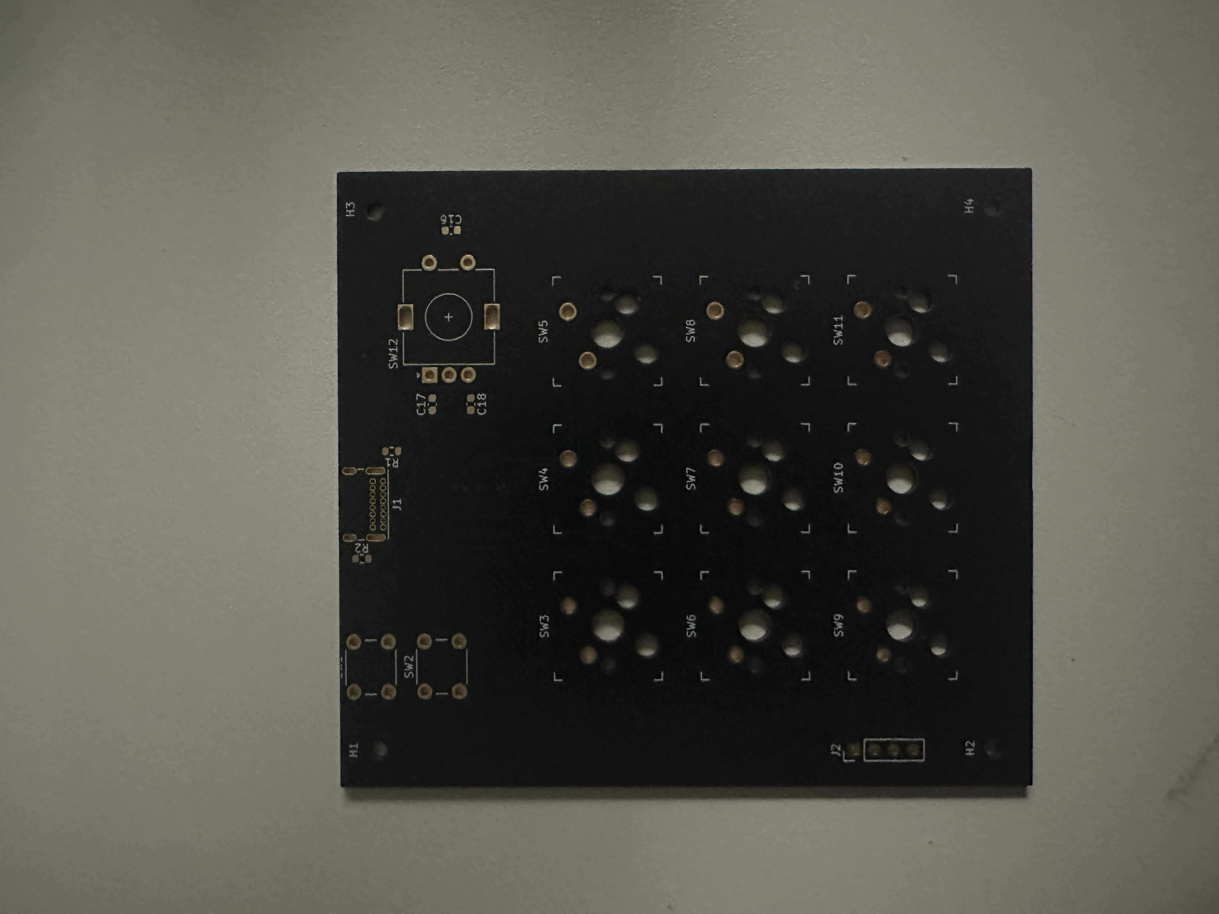 |
Bare 2-layer board from JLCPCB, before assembly.
Full component list: docs/bom.csv — 70 parts across 19 line items.
Schematic as PDF: docs/schematic.pdf.
hardware/      KiCad project — schematic, board, and project-local footprint library
fabrication/   Gerbers and drill files as sent to the fab, plus the board outline DXF
docs/          Schematic PDF, BOM, board photos
hardware/keyswitches.pretty holds the Kailh hot-swap footprint and is wired up
through hardware/fp-lib-table, so the project opens with all footprints resolved
on a clean KiCad install.
Open hardware/macro-keypad.kicad_pro in KiCad 10. To re-order boards, zip the
contents of fabrication/gerbers/ and upload — 2 layers, 1.6 mm, HASL is fine.
The board is fabricated and I'm hand-soldering the switches, diodes, and supporting components. Firmware is in progress: a USB HID keyboard with matrix scanning and debounce on the RP2040. Bring-up and testing come once assembly is done.
D in SOD-123. They need a real
part number in the BOM (1N4148W or equivalent) before anyone else can build this.| Qty | Value | Footprint | References |
|---|---|---|---|
| 19 | 100nF | Capacitor_SMD:C_0603_1608Metric | C3, C4, C5, C10, C11, C12, C15, C19, C20, C21, C22, C23, C24, C25, C26, C27 +3 |
| 9 | D | Diode_SMD:D_SOD-123 | D1, D2, D3, D4, D5, D6, D7, D8, D9 |
| 9 | SW_Push | keyswitches:Kailh_socket_MX_optional | SW3, SW4, SW5, SW6, SW7, SW8, SW9, SW10, SW11 |
| 9 | WS2812B | LED_SMD:LED_SK6812MINI_PLCC4_3.5x3.5mm_P1.75mm | D10, D11, D12, D13, D14, D15, D16, D17, D18 |
| 4 | MountingHole | MountingHole:MountingHole_2.2mm_M2 | H1, H2, H3, H4 |
| 3 | 10nF | Capacitor_SMD:C_0603_1608Metric | C16, C17, C18 |
| 2 | 10uF | Capacitor_SMD:C_0603_1608Metric | C1, C2 |
| 2 | 15pF | Capacitor_SMD:C_0603_1608Metric | C13, C14 |
| 2 | 5.1k | Resistor_SMD:R_0603_1608Metric | R1, R2 |
| 2 | SW_Push | Button_Switch_THT:SW_PUSH_6mm | SW1, SW2 |
| 1 | 1k | Resistor_SMD:R_0603_1608Metric | R3 |
| 1 | 1uF | Capacitor_SMD:C_0603_1608Metric | C7 |
| 1 | AP2112K-3.3 | Package_TO_SOT_SMD:SOT-23-5 | U3 |
| 1 | Conn_01x04 | Connector_PinHeader_2.54mm:PinHeader_1x04_P2.54mm_Vertical | J2 |
| 1 | Crystal_GND24 | Crystal:Crystal_SMD_3225-4Pin_3.2x2.5mm | Y1 |
| 1 | RP2040 | Package_DFN_QFN:QFN-56-1EP_7x7mm_P0.4mm_EP3.2x3.2mm | U1 |
| 1 | RotaryEncoder_Switch | Rotary_Encoder:RotaryEncoder_Alps_EC11E-Switch_Vertical_H20mm | SW12 |
| 1 | USB_C_Receptacle_USB2.0_14P | Connector_USB:USB_C_Receptacle_GCT_USB4085 | J1 |
| 1 | W25Q16JVSS | Package_SO:SOIC-8_5.3x5.3mm_P1.27mm | U2 |


nthclrd/picflash
Programmeur PIC open source en Rust : remplace MPLAB IPE/XC8 pour les PIC16, pilote les PICkit 4/5/Basic ou une carte RP2040 maison (KiCad)

ZachS07/RP2040-IMU-Altimeter-PCB
Custom PCB motion and altitude data logger. RP2040 microcontroller with onboard IMU, barometric sensor, and flash storage. It's suitable for model rockets, drones, and other applications.

C-yue28/Plant-Monitor
ML-powered plant monitor, tracking metrics such as temperature, humidity, soil moisture, etc to inform plant watering behavior.

Cherry-Blossom-Development/GreywireStudio
GreywireStudio - a combined software/hardware product

draarivpatel-ui/helios-cad-forge
Helios-6 is a parametric dual-axis solar tracker gimbal, OpenSCAD + watertight STL mesh generator, Spencer (1971) solar ephemeris calculator, and KiCad 8 RP2040 + INA219 telemetry node.

JesseLevine727/AirNote
A touchless musical instrument built around a fully integrated RP2040, VL53L1X distance sensor and MAX98357A speaker amplifier. One hand selects eleven pentatonic notes over two octaves.
It measures 80 × 90 mm and has 2 copper layers, 1.6 mm thick.
70 parts, built around the RP2040, W25Q16JVSSIQ, AP2112K-3.3 and WS2812B. The full list of its parts is on this page, with links to each part's symbol and footprint where PCBKit's library has them.
From the johnppilli/macro-keypad repository on GitHub, at the commit this page was made from: the board is hardware/macro-keypad.kicad_pcb and its schematic hardware/macro-keypad.kicad_sch. PCBKit opens the board in the browser, with nothing to install.
Its repository states no licence, so its author keeps all rights: ask johnppilli before reusing the design.