2 layers305.1 × 161.5 mm
BeanBoard
PainfulDiodes/BeanBoard
QWERTY Keyboard, simple LCD display and GPIO for BeanZee
167 parts11MIT

 JohnDMcMaster/8051dumper27
by NF6X. Forked from: https://gitlab.com/NF6X_Retrocomputing/8051dumper
8051dumper is an open-source printed circuit board by JohnDMcMaster, from the JohnDMcMaster/8051dumper repository on GitHub. It is a 4-layer board of 101.6 × 76.2 mm with 41 parts on 51 nets, routed with 346 tracks and 34 vias.
It is built around the AT28C256-15PU, SN74LS373N and TTL-232R-5V-AJ, with the WP7113GD among its other parts. Its parts include 14 resistors, 6 capacitors, 4 switches, 3 ICs and 3 transistors.


This board and firmware allow the mask-programmed ROM contents to be dumped from Intel 8051 processors and derivatives/clones which do not include ROM readout protection mechanisms.
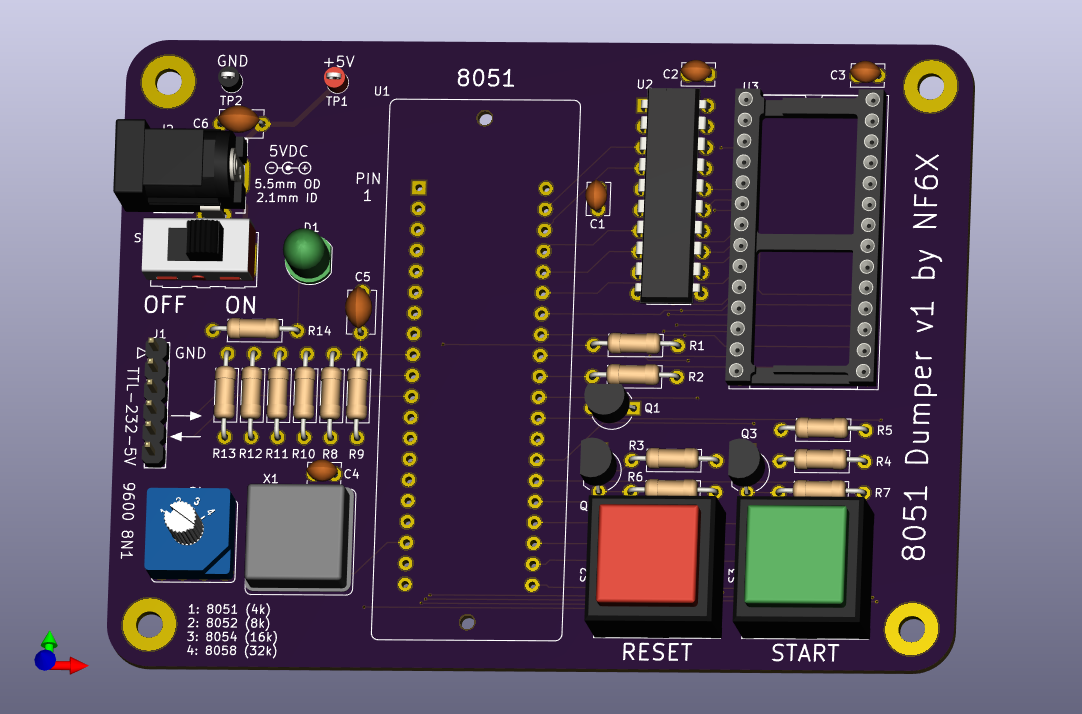
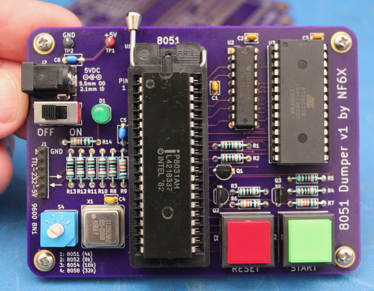
I wanted to dump out the firmware from the internal mask ROM of a Signetics SCN8051H microcontroller in an ailing Micropolis 1325 (AKA DEC RD53-A) hard disk drive. None of my programmers are able to do that, but there's a tricky way to get early 8051 microcontrollers to dump out their own firmware. I made this board to do it... and over-engineered the heck out of it, because why not! This technique has been around for a long time. I didn't invent it. I just made this board because I'd rather lay out a board than wire up stuff on a breadboard.
The 8051 has a pin called EA# which tells it whether to fetch code from its internal ROM (which is programmed at the metal mask layer at chip fabrication time) or an external ROM. The trick is to put the 8051 into a circuit which initially pulls EA# low, so that the 8051 will boot from an external ROM with our dumper code in it. That code immediately jumps out of the 4k address range that is mapped to internal ROM when EA# is high, and then uses a GPIO pin to pull its own EA# pin high and re-enable the internal mask ROM. At that point, the 8051 conveniently fetches program memory accesses in the 0x0000-0x0FFF range from the internal ROM, and fetches program memory accesses outside that range from our external ROM. The special dumper code on our external ROM can then use the MOVC function to read internal ROM bytes, and then dump them out somehow (such as with the built-in serial port).
The 8052, 8054 and 8058 chips have larger internal ROM spaces, but otherwise work the same way. Just for the heck of it, I put a knob on this board to tell its firmware how much of the internal ROM space it should try to dump.
Later 8051 derivatives added features to prevent dumping their internal ROMs easily, sunce as simply latching EA# at reset time so that changing it later doesn't do anything. This board can't work with any of those. It's only intended to work with original Intel 8051 microcontrollers and exactl clones whose EA# pins behave the same way.
You're on your own for assembling the board. You will need to program the
board's firmware into an AT28C256 (or plug-in equivalent) 32k x 8 (E(E))PROM.
Use the firmware/8051dumper_filled.hex image. This image contains the
necessary firmware for the 8051dumper board, with its unused areas filled with a
recognizable pattern to help you identify whether any given device under test is
dumping internal or external ROM contents.
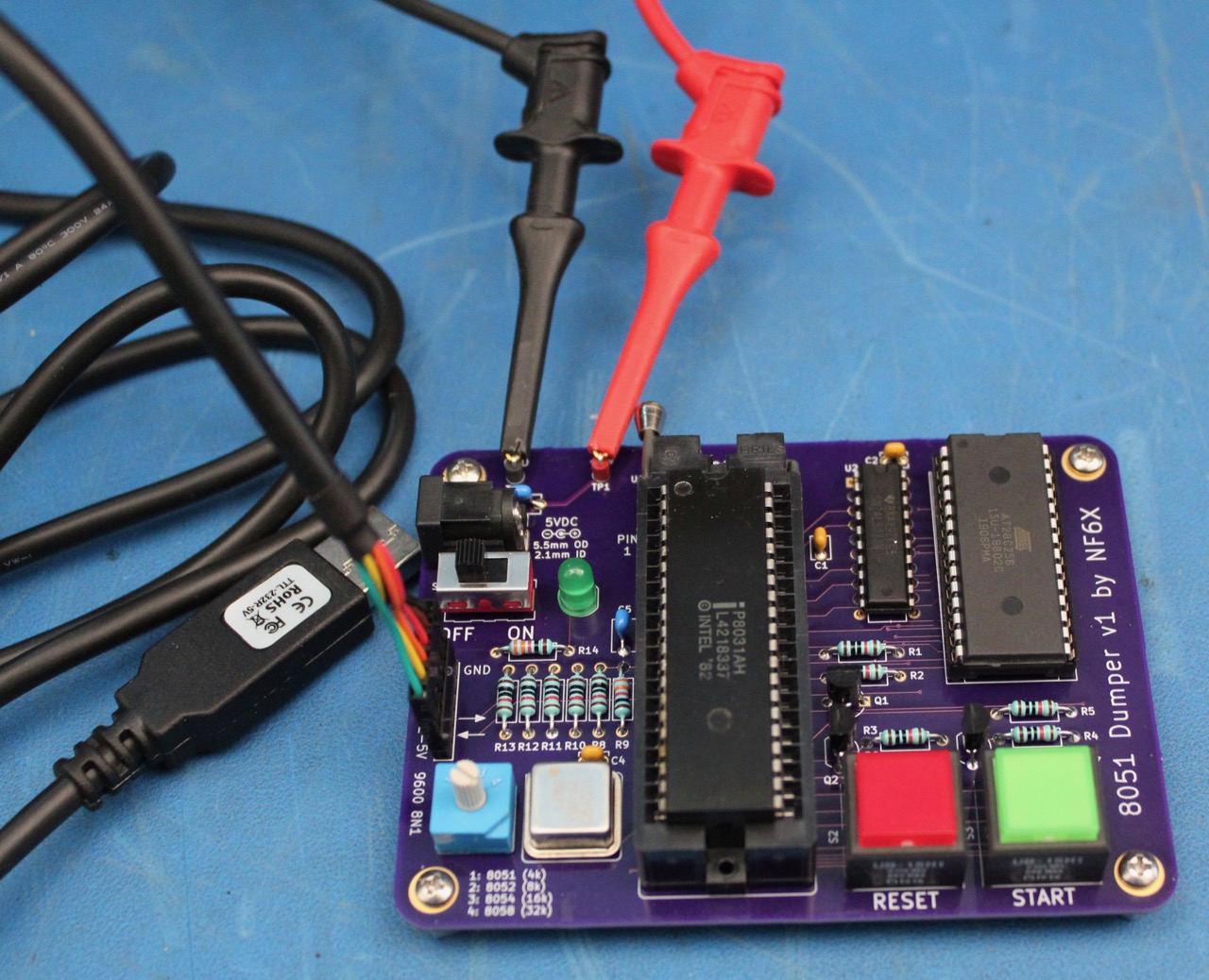
This board requires an external source of clean, regulated 5 VDC power, and some sort of asynchronous serial interface with 5V TTL/CMOS signal levels. An FTDI TTL-232R-5V cable can be pluged right into the header, or you can use clip leads. The silkscreen markings identify the ground pin and the two data pins.
There is no reverse-polarity protection, power regulation, or overvoltage protection on this board. You need to connect the power correctly, or you will fry stuff. You can supply power through either the barrel jack or with clip leads connected to the two test points.
Set your serial interface for 9600 baud, 8 data bits, no parity, and no flow control. Use a terminal emulator or any other suitable software which can capture the 9600 baud stream from 8051dumper.
Always make sure that the power switch is OFF before installing or removing a device under test from 8051dumper.
If all goes well, when you turn on the board with a working 8051 (or other
MCS-51 series) microcontroller
installed, the green START button will begin blinking and the serial port will
spit out 8051dumper v1.0 by NF6X. If that doesn't happen at power-on, try
pressing the red RESET button to reset the microcontroller manually. If it still
doesn't happen, start debugging. Maybe the socket isn't making good contact?
Maybe, well, literally anything else has gone wrong?
Once the green START button is blinking, set the knob to the appropriate ROM size and then press the green START button to begin the dump. While the dump is in progress, the red RESET button will flash rapidly. When the dump is done, the red RESET button will go dark and the green START button will light up. Now you can turn off the board, or press RESET to do it all over again.
The 8051dumper output is in Intel hex format. If you try dumping beyond the end of the internal ROM, or if you try dumping from a device which latches EA# at reset time, then some or all of the output will be from the 8051dumper's own external ROM instead of the device under test's internal ROM. To help you indentify when this happens, the unused spaces of 8051dumper's ROM are filled with a pattern which is recognizable in either hexadecimal or ASCII representations, and repeats every 16 bytes:
| Qty | Value | Footprint | References |
|---|---|---|---|
| 10 | 10k | Resistor_THT:R_Axial_DIN0207_L6.3mm_D2.5mm_P10.16mm_Horizontal | R1, R2, R3, R4, R5, R8, R10, R11, R12, R13 |
| 4 | 0.1uF | Capacitor_THT:C_Disc_D3.8mm_W2.6mm_P2.50mm | C1, C2, C3, C4 |
| 4 | 332 | Resistor_THT:R_Axial_DIN0207_L6.3mm_D2.5mm_P10.16mm_Horizontal | R6, R7, R9, R14 |
| 3 | 2N3906 | Package_TO_SOT_THT:TO-92_Inline_Wide | Q1, Q2, Q3 |
| 2 | 10uF | Capacitor_THT:C_Disc_D5.1mm_W3.2mm_P5.00mm | C5, C6 |
| 1 | 11.0592 MHz | Oscillator:Oscillator_DIP-8 | X1 |
| 1 | 8051 | Package_DIP:DIP-40_W15.24mm_ZIF_Socket_Aries_40-6554-10 | U1 |
| 1 | AT28C256-15PU | Package_DIP:DIP-28_W15.24mm_Socket | U3 |
| 1 | CK_1101M2S3CQE2 | Button_Switch_THT:SW_CK_1101M2S3CQE2 | S1 |
| 1 | CUI_PJ-050AH | Connector_BarrelJack:BarrelJack_Horizontal_CUI_PJ-050AH | J2 |
| 1 | Copal_S-2150 | Button_Switch_THT:Copal_S-2150 | S4 |
| 1 | NKK_UB15SKG035C-CC | Button_Switch_THT:SW_NKK_UB15SKG035C-CC | S2 |
| 1 | NKK_UB15SKG035F-FF | Button_Switch_THT:SW_NKK_UB15SKG035F-FF | S3 |
| 1 | SN74LS373N | Package_DIP:DIP-20_W7.62mm | U2 |
| 1 | TTL-232R-5V | Connector_PinHeader_2.54mm:PinHeader_1x6_P2.54mm_Vertical_Unshrouded | J1 |
| 1 | TestPoint_Mini_Black | TestPoint:TestPoint_Keystone_5001 | TP2 |
| 1 | TestPoint_Mini_Red | TestPoint:TestPoint_Keystone_5000 | TP1 |
| 1 | WP7113GD | LED_THT:LED_D5.0mm_Green_Kingbright_WP7113 | D1 |
The 36 most common of 41 parts.
PainfulDiodes/BeanBoard
QWERTY Keyboard, simple LCD display and GPIO for BeanZee

Ken-2511/desk-timer
My tiny project using KiCad to create a PCB for desk-timer (reminding me to drink water or something)

costarc/msxcart_flash32k
A MSX 32K EEPROM AT28C256 cartridge rewritable by software.

yoppeh/eeprom-programmer
An Arduino Nano sketch and schematic for an Atmel 28cx programmer.

rosco-6502/rosco_6502
Design, documentation and software for the Really Old School Computer (6502)


napicella/8-bit-computer
Resources for an 8 bit computer based on the 6502 micro processor

rosco-m68k/rosco_m68k
Design, documentation and software for the Really Old School Computer (M68K)
It measures 101.6 × 76.2 mm and has 4 copper layers, 1.6 mm thick.
41 parts, built around the AT28C256-15PU, SN74LS373N, TTL-232R-5V-AJ and WP7113GD. The full list of its parts is on this page, with links to each part's symbol and footprint where PCBKit's library has them.
From the JohnDMcMaster/8051dumper repository on GitHub, at the commit this page was made from: the board is pcb/8051dumper.kicad_pcb. PCBKit opens the board in the browser, with nothing to install.
Its repository states no licence, so its author keeps all rights: ask JohnDMcMaster before reusing the design.