2 layers390 × 78.2 mm
MBO
shanteacontrols/OpenDeck
A platform for building interactive control and sensing devices using MIDI and OSC built with Zephyr RTOS.
61 parts960Apache-2.0

 joebmz98/MC8P-Midi-Controller8
8 Potentiometer Standalone MIDI Controller based on the Teensy 4.0.
MC8P Midi Controller is an open-source printed circuit board by joebmz98, from the joebmz98/MC8P-Midi-Controller repository on GitHub, published under the MIT licence. It is a 2-layer board of 155 × 288 mm with 61 parts on 44 nets, routed with 267 tracks and 0 vias.
Its parts include 12 capacitors, 6 resistors, 4 switches, 2 connectors and 1 IC. It belongs with the audio and music boards and the NXP (LPC, Kinetis, i.MX RT) boards of this library.
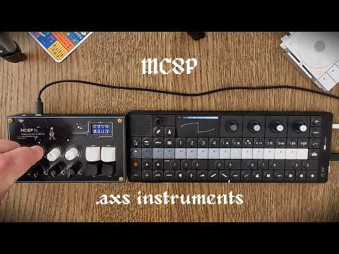
A customizable, open-source MIDI controller with 8 potentiometers, each supporting Up to 10 assignable MIDI CCs per Potentiometer, built around the Teensy 4.0 for high-performance MIDI control.

| Component | Qty | Notes | Links |
|---|---|---|---|
| Teensy 4.0 | 1 | Main microcontroller | The Pi Hut (UK) |
| SSD1306 OLED (128×64) | 1 | I²C interface | AliExpress |
| B100K Vertical Potentiometer | 8 | Linear taper | Example |
| 3.5mm Stereo Socket (PJ307) | 1 | MIDI TRS Type A | Example |
| Kailh Switches | 4 | For menu navigation | — |
| Kailh Switch Caps | 4 | For Kailh switches | AliExpress |
| Potentiometer Knobs | 8 | For B100K potentiometers | AliExpress |
| DC-005 Barrel Jack Socket | 1 | 5V DC power input | AliExpress |
| 10nF Ceramic Capacitors | 8 | Potentiometer filtering | — |
| 10k Resistors | 4 | Pull-down for buttons | — |
| 220Ω Resistors | 2 | For MIDI Circuitry | — |
| 100nF Ceramic Capacitor | 1 | Power rail stabilisation | — |
| 10uF Ceramic Capacitor | 1 | Power rail stabilisation | — |
| 10uF Electrolytic Capacitor | 1 | 5V input stability | — |
| 100uF Electrolytic Capacitor | 1 | Power rail stabilisation | — |
PCB Only – For custom builds → Purchase from my Tindie store
.ino file in the Arduino IDE| Button | Primary Function |
|---|---|
| ASSIGN | Navigate backward, cancel actions, return to previous screens |
| ENTER | Confirm selections, activate temporary override mode |
| PREV | Move up or decrease values |
| NEXT | Move down or increase values |
The interface is organized into several screens accessible from the main display:
MAIN SCREEN → MENU → SETTINGS → various configuration screens
This is your default operating view. The screen displays eight circular indicators, one for each potentiometer, showing current MIDI values (0-127). Each circle fills proportionally to the value being sent.
From the main screen:
When you press and hold ENTER on the main screen, the controller enters temporary override mode. In this mode, all potentiometer adjustments are temporary. When you release ENTER, the controller returns to the stored values and activates catch up mode, where potentiometers must pass through their stored positions before taking control again.
Press ASSIGN from the main screen to reach the menu. Use PREV and NEXT to scroll through options:
Press ENTER to select an option, or press ASSIGN to return to the main screen.
This screen lets you configure up to 10 MIDI messages per potentiometer.
Navigation flow:
Parameters you can edit for each message:
Editing values: When editing a parameter, use potentiometer 8 to smoothly adjust the value across its full range. The selected parameter flashes to indicate edit mode.
Navigation within Assign Screen:
Add/Remove messages:
From the menu, select Settings to access:
Assign Settings – Choose which potentiometer (1-8) to use for editing values in the Assign screen. Use PREV/NEXT to change the selection.
Display Settings – Toggle the display inversion between normal and inverted. Press ENTER to enter edit mode, then use PREV or NEXT to toggle between Yes and No. Press ENTER again to save, or ASSIGN to cancel.
About – View firmware version and device information.
Factory Reset – Restore all settings to default values. A confirmation screen prevents accidental resets.
When saving changes or performing a factory reset, a popup screen appears asking for confirmation. Use PREV/NEXT to toggle between Y (Yes) and N (No), then press ENTER to confirm or ASSIGN to cancel.
Adafruit_SSD1306 (OLED)Adafruit_GFX (Adafruit UI Design)MIDI (MIDI)ResponsiveAnalogRead (Potentiometer Smoothing)Picopixel (Picopixel Font)Owner's Manual: https://docs.google.com/document/d/1LK1hT5nvRXzgEnc-npS-HN6GpmSG35B1l2-KNDyIfV0/edit?usp=sharing
MIT License – Open-source for personal & commercial use
PCBway very kindly offered to sponsor this project and have sent me some more stock for the shop. Thank you to PCBway for supporting this passion project of mine. Emily from the marketing department reached out to me when I first launched the product and store and very kindly offered to sponsor the project. Both working with them and using their services was really easy. All I needed to do was export my PCB gerber files, drag and drop them on the 'PCB Instant Quote' page and send it off for approval. I received my order a week later and was very happy with the quality of the PCBs. Thank you again PCBway for your support.
You can find their website here: https://www.pcbway.com/
| Qty | Value | Footprint | References |
|---|---|---|---|
| 9 | , , , , , , , , | ||
| 8 | B100k | DIYSynthMNL:Potentiometer_RV09_BigPads | RV1, RV2, RV3, RV4, RV5, RV6, RV7, RV8 |
| 8 | C_Generic | Capacitor_THT:C_Axial_L3.8mm_D2.6mm_P7.50mm_Horizontal | C1, C2, C3, C4, C5, C6, C7, C8 |
| 4 | 10k_0402 | PCM_4ms_Resistor:R_Axial_DIN0207_L6.3mm_D2.5mm_P7.62mm_Horizontal | R1, R2, R3, R4 |
| 3 | LOGO | MC8P_BITMAP_FOOTPRINTS:MC8P_PXLART_SPACE_FMASK_45X40 | G***, G***, G*** |
| 2 | 220R | PCM_4ms_Resistor:R_Axial_DIN0207_L6.3mm_D2.5mm_P7.62mm_Horizontal | R5, R6 |
| 1 | 100nF | Capacitor_THT:C_Disc_D5.0mm_W2.5mm_P5.00mm | C9 |
| 1 | 100uF | Capacitor_THT:CP_Radial_D4.0mm_P1.50mm | C11 |
| 1 | 10uF | Capacitor_THT:C_Disc_D5.0mm_W2.5mm_P5.00mm | C10 |
| 1 | 10uF_4x5.3_10V | Capacitor_THT:CP_Radial_D4.0mm_P1.50mm | C12 |
| 1 | 5V | Connector_BarrelJack:BarrelJack_GCT_DCJ200-10-A_Horizontal | J2 |
| 1 | ASSIGN | Button_Switch_Keyboard:SW_Cherry_MX_1.00u_PCB | SW1 |
| 1 | ENTER | Button_Switch_Keyboard:SW_Cherry_MX_1.00u_PCB | SW2 |
| 1 | LOGO | MC8P_BITMAP_FOOTPRINTS:MC8P_MANUAL_QR_SLKSCR_20X20 | G*** |
| 1 | LOGO | AXS_LOGO_KICAD:AXS_LOGO_FMASK_43X43 | G*** |
| 1 | LOGO | AXS_LOGO_KICAD:AXS_LOGO_FMASK_20X20 | G*** |
| 1 | LOGO | pcbWayLogo:pcbWay_LOGO_FSILK_15mm | G*** |
| 1 | MIDI OUT | audioConnectors_Edit:Jack_3.5mm_CUI_SJ1-3525N_Horizontal_edit | J1 |
| 1 | NEXT | Button_Switch_Keyboard:SW_Cherry_MX_1.00u_PCB | SW4 |
| 1 | PREV | Button_Switch_Keyboard:SW_Cherry_MX_1.00u_PCB | SW3 |
| 1 | Teensy4.0 | teensy:Teensy40 | U1 |
| 1 | ~ | SSD1306_footprint:SSD1306_OLED_Module | SSD1306 |
The 50 most common of 61 parts.
shanteacontrols/OpenDeck
A platform for building interactive control and sensing devices using MIDI and OSC built with Zephyr RTOS.

Neumi/open_echo
Open Source echo sounder / depth sounder / SONAR for bathymetry and research. Arduino based and compatible.

StuckAtPrototype/AirCube
Works standalone out of the box. Pairs with Home Assistant in minutes. Other platforms are supported through community-contributed extensions.

TeXitoi/keyseebee
KeySeeBee is a split ergo keyboard. It is only 2 PCB (so the name) with (almost) only SMD components on it. It's only a keyboard, no LED, no display, nothing more than keys and USB.


Jeija/esp8266-smartwatch
ESP8266 DIY WiFi Smartwatch with MPU-9250, RTC, OLED, FT232, ...


It measures 155 × 288 mm and has 2 copper layers, 1.6 mm thick.
61 parts. The full list of its parts is on this page, with links to each part's symbol and footprint where PCBKit's library has them.
From the joebmz98/MC8P-Midi-Controller repository on GitHub, at the commit this page was made from: the board is MC8P_MIDI_CONTROLLER_KiCad/MC8P_MIDI_CONTROLLER/MC8P_MIDI_CONTROLLER.kicad_pcb and its schematic MC8P_MIDI_CONTROLLER_KiCad/MC8P_MIDI_CONTROLLER/MC8P_MIDI_CONTROLLER-backups/MC8P_MIDI_CONTROLLER-2026-04-15_142720/MC8P_MIDI_CONTROLLER.kicad_sch. PCBKit opens the board in the browser, with nothing to install.
Its repository publishes it under the MIT licence: you may reuse it on that licence's terms (keep the author's notice, and for a copyleft licence share your changes alike).