4 layers120 × 113 mm
Voron Klipper Board
VoronDesign/Voron-Hardware
Cool Hardware designed by the Voron Design group
360 parts1.1kGPL-3.0

 joebmz98/DCLK
Dual MIDI Clock based on the Sim'n Tonic Nome II
DCLK MIDI Clock is an open-source printed circuit board by joebmz98, from the joebmz98/DCLK repository on GitHub, published under the MIT licence. It is a 2-layer board of 125 × 213 mm with 76 parts on 61 nets, routed with 447 tracks and 66 vias.
It is built around the 74AHCT125D and BAT43. Its parts include 18 resistors, 10 capacitors, 7 connectors, 4 diodes and 3 ICs. It belongs with the audio and music and lEDs and displays boards of this library.


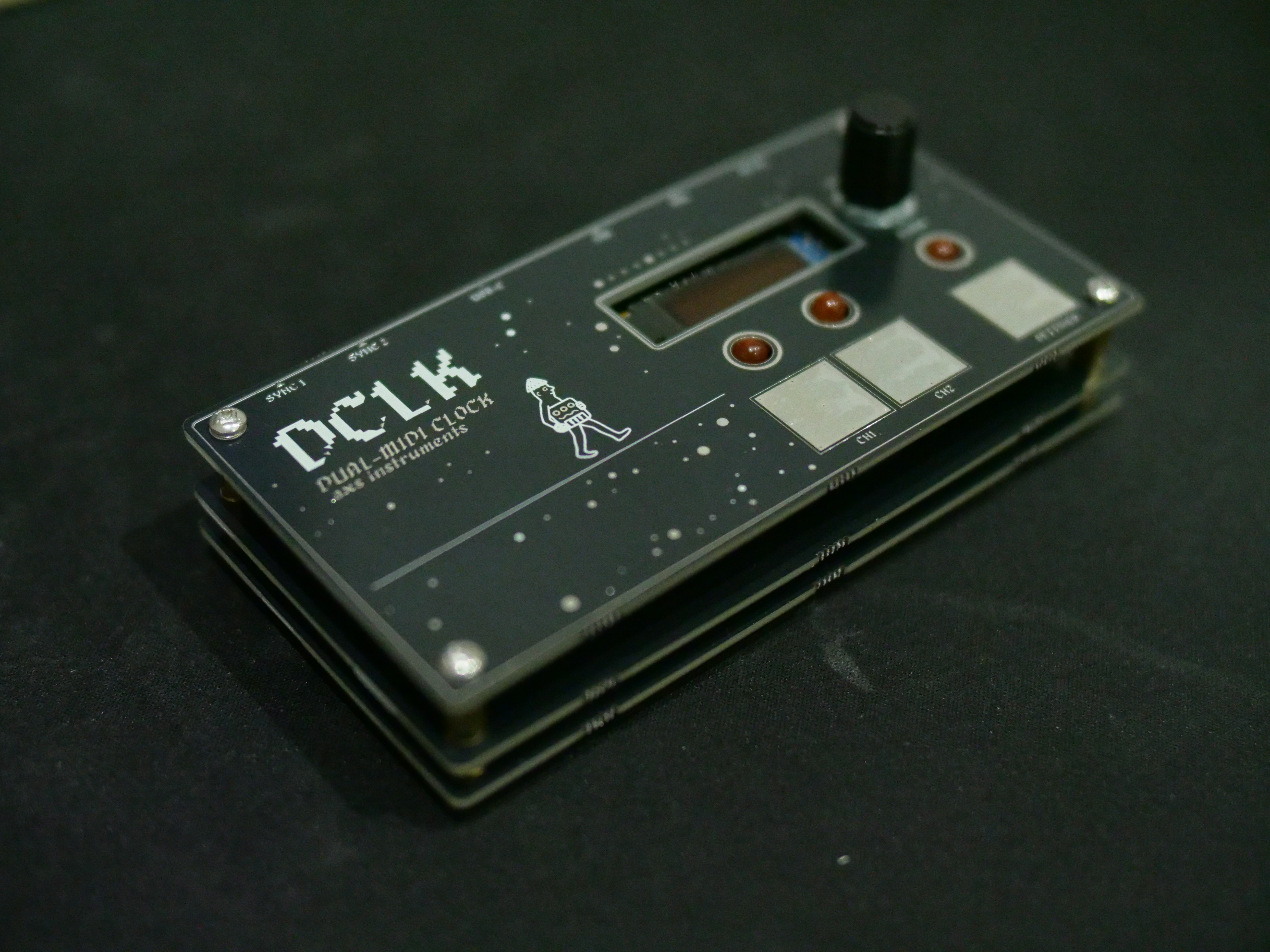
.axs instruments · Firmware v1.6.3 · Hardware v1.0
DCLK is a dual MIDI clock built around an STM32F411 Black Pill. It sends MIDI clock to two TRS (Type A) outputs and over USB MIDI, with quantised start/stop and a separate clock divider for each output, so two machines can be dropped in and out of a jam on the bar.
Flash the latest release straight from Chrome or Edge on a computer. No software to install. Your saved settings are kept. Flasher source: DCLK-Flasher.
Windows needs a one-time WinUSB driver (Zadig); the flasher's Troubleshooting section walks through it.
| Control | Action |
|---|---|
| Encoder (main screen) | Set tempo |
| CH1 / CH2 | Start or stop that output. Press again while waiting to cancel |
| Settings | Open the menu · back · cancel an edit |
| Encoder push | Select / confirm in the menu |
Clock, Start and Stop are MIDI System Real-Time messages, so they carry no MIDI channel: "CH1" and "CH2" mean the two output jacks.
LEDs
Main screen: a white CH1 / CH2 tab appears along the top while that output plays, and disappears when it stops (firmware 1.6.2 and later). Below them are the tempo and four beat bars; the current beat stands taller. The bars and the BEAT LED move while an output plays, and (from 1.6.3) while a USB host plays in HOST mode even with both outputs off.
Menus
| Menu | Settings |
|---|---|
| LEDS | Brightness: LO / MID / HI |
| MIDI | WAIT LEN · STOP Q · CH1 DIV · CH2 DIV · USB OUT |
| SYNC | SYNC 1 / SYNC 2 pulses per quarter note: 1 / 2 / 4 / 8 / 12 / 24 |
| SCREEN | SAVER: OFF / 1 / 5 / 10 / 30 min |
| MONITOR | USB and clock diagnostics; encoder push toggles a USB test note (C4, ch 1) |
| UPDATE | Restart into DFU mode for the web flasher (push the encoder to confirm, SETTINGS cancels) |
| ABOUT | Product, maker and firmware version |
| Connector | Use |
|---|---|
| USB‑C (Black Pill) | USB MIDI clock, power, firmware updates |
| MIDI OUT 1 / 2 | 3.5 mm TRS, Type A |
| SYNC OUT 1 / 2 | 3.5 mm TRS, 5 V: tip = clock pulse, ring = run gate (high while playing) |
| DC jack | 5 V, centre positive |
KiCad 9 project in build/DCLK-MIDI-Clock/, with JLCPCB-ready Gerbers,
BOM and placement files in production/. Custom footprints are in
lib/DCLK.pretty/.
Main parts: STM32F411CEU6 Black Pill, SSD1306 128×32 I²C OLED, CAP1206 touch controller, Alps EC11E encoder with switch, 2× CUI SJ1‑3525N TRS jacks, GCT DCJ200 DC jack, 3× 5 mm LEDs.
| Function | Pin |
|---|---|
| MIDI OUT 1 / 2 (TX) | PA9 (USART1) / PA2 (USART2) |
| SYNC 1 clock / run | PA8 / PB15 (via 74AHCT125 to 5 V) |
| SYNC 2 clock / run | PA5 / PA4 (via 74AHCT125 to 5 V) |
| CH1 / CH2 / Settings touch pads | CAP1206 CS1 / CS2 / CS3 (I²C 0x28) |
| CAP1206 ALERT# | PB12 |
| Encoder A / B / push | PB4 / PB5 / PB13 |
| LED CH1 / CH2 / BEAT | PB8 / PB9 / PA6 (PWM) |
| OLED + CAP1206 SDA / SCL | PB7 / PB6 |
The sketch is src/dclk_midi_clock/dclk_midi_clock.ino (Arduino IDE).
0x08000000, with no HID or UF2 bootloader offset.To publish a release, use Sketch > Export Compiled Binary, copy the
.hex into the flasher repo's firmware/ folder and update its
manifest.json.
src/dclk_midi_clock/   firmware sketch, compiled builds, font
legacy/                every firmware release (hex, bin, source)
build/DCLK-MIDI-Clock/ KiCad project and production files
lib/DCLK.pretty/       custom footprints
assets/ artwork (polarity marking)MIT. See LICENSE. © 2026 .axs instruments
| Qty | Value | Footprint | References |
|---|---|---|---|
| 12 | , , , , , , , , , , , | ||
| 12 | MouseBite_Tab | mouse bites:MouseBite_Tab_5mm_Gap2mm | MB**, MB**, MB**, MB**, MB**, MB**, MB**, MB**, MB**, MB**, MB**, MB** |
| 4 | 100k | Resistor_SMD:R_0402_1005Metric | R11, R12, R13, R14 |
| 4 | 1k | Resistor_SMD:R_0402_1005Metric | R15, R16, R17, R18 |
| 4 | 33R | PCM_4ms_Resistor:R_0603 | R1, R2, R3, R4 |
| 3 | 100nF | Capacitor_SMD:C_1206_3216Metric | C1, C6, C10 |
| 3 | 10nF | Capacitor_SMD:C_1206_3216Metric_Pad1.33x1.80mm_HandSolder | C7, C8, C9 |
| 3 | 330R | PCM_4ms_Resistor:R_0603 | R7, R8, R9 |
| 3 | LED | LED_THT:LED_D5.0mm | D2, D3, D4 |
| 2 | 10uF | Capacitor_SMD:C_1206_3216Metric_Pad1.33x1.80mm_HandSolder | C2, C4 |
| 2 | 4k7 | PCM_4ms_Resistor:R_0603 | R5, R6 |
| 2 | MIDI OUT | audioConnectors_Edit:Jack_3.5mm_CUI_SJ1-3525N_Horizontal_edit | J1, J3 |
| 1 | 100nF | Capacitor_SMD:C_1206_3216Metric_Pad1.33x1.80mm_HandSolder | C3 |
| 1 | 100uF | Capacitor_THT:CP_Radial_D4.0mm_P1.50mm | C5 |
| 1 | 10k | PCM_4ms_Resistor:R_0603 | R10 |
| 1 | 74AHCT125 | Package_SO:SOIC-14_3.9x8.7mm_P1.27mm | U3 |
| 1 | BAT43 | Diode_SMD:D_SOD-123 | D1 |
| 1 | CAP1206-x-SL | Package_SO:SOIC-14_3.9x8.7mm_P1.27mm | U2 |
| 1 | Conn_02x04_Odd_Even | Connector_PinHeader_2.54mm:PinHeader_2x04_P2.54mm_Vertical_SMD | J6 |
| 1 | Conn_02x04_Odd_Even | Connector_PinSocket_2.54mm:PinSocket_2x04_P2.54mm_Vertical | J5 |
| 1 | Jack-DC | Connector_BarrelJack:BarrelJack_GCT_DCJ200-10-A_Horizontal | J2 |
| 1 | LOGO | AXS_LOGO:AXS_LOGO_NOTEXT_10mm_FSILK | G*** |
| 1 | LOGO | dclk:DCLK-Back-Panel_FSILK | G*** |
| 1 | LOGO | dclk:DCLK-Front-Panel_FMASK | G*** |
| 1 | LOGO | dclk:DCLK-Front-Panel_FSILK | G*** |
| 1 | RotaryEncoder_Switch_MP | Rotary_Encoder:RotaryEncoder_Alps_EC11E-Switch_Vertical_H20mm_MountingHoles | SW4 |
| 1 | SYNC 1 OUT | PJ307-TRS:PJ307-TRS-SOCKET | J7 |
| 1 | SYNC 2 OUT | PJ307-TRS:PJ307-TRS-SOCKET | J8 |
| 1 | ~ | SSD1306:SSD1306-128x32 | SSD1306 |
| 1 | ~ | blackpill:Z_module_black_pill_STM32F411 | U1 |
The 72 most common of 76 parts.
It measures 125 × 213 mm and has 2 copper layers, 1.6 mm thick.
76 parts, built around the 74AHCT125D and BAT43. The full list of its parts is on this page, with links to each part's symbol and footprint where PCBKit's library has them.
From the joebmz98/DCLK repository on GitHub, at the commit this page was made from: the board is build/DCLK-MIDI-Clock/DCLK-MIDI-Clock.kicad_pcb and its schematic build/DCLK-MIDI-Clock/DCLK-MIDI-Clock.kicad_sch. PCBKit opens the board in the browser, with nothing to install.
Its repository publishes it under the MIT licence: you may reuse it on that licence's terms (keep the author's notice, and for a copyleft licence share your changes alike).
VoronDesign/Voron-Hardware
Cool Hardware designed by the Voron Design group


ravinrabbid/DonCon2040
RP2040 based firmware and hardware for DIY Taiko no Tatsujin Drum Controllers

Testbild-synth/HAGIWO_arduino_oscillator
4HP through hole version of the HAGIWO FM/additive/chord oscillator with mode switch and gain input.

Testbild-synth/Hagiwo_009_030_sequencer
A through-hole PCB conversion of HAGIWO's 6 channel eurorack gate sequencer. Includes Gerbers, Code and building instructions.

bvarner/pi485
An open-source TTL UART <-> RS485 converter, intended for a Raspberry Pi or Arduino

Testbild-synth/HAGIWO-029-033-Eurorack-quantizer
Through hole PCB version of the HAGIWO Dual Quantizer/SH101 Sequencer Eurorack Module-.