
2 layers33.7 × 97.8 mm
HAN ESP TSS721
UtilitechAS/amsreader-firmware
ESP8266 and ESP32 compatible firmware to read, interpret and publish data to MQTT from smart electrical meters, both DLMS and DSMR is supported
29 parts470

 jocobuilds/easy-led-panel1
Build and program an LED panel the easy way!
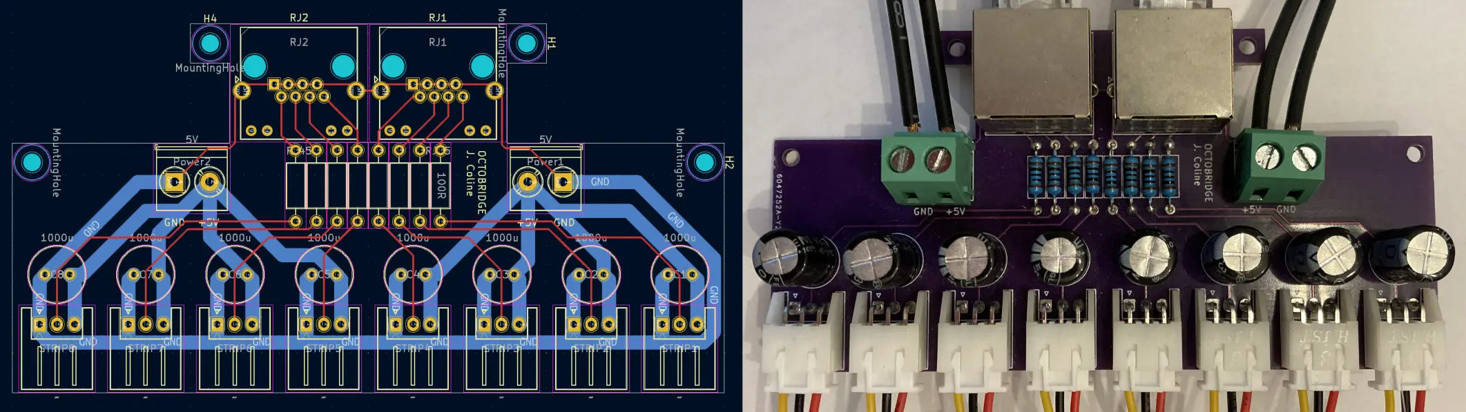
Octobridge is an open-source printed circuit board by jocobuilds, from the jocobuilds/easy-led-panel repository on GitHub, published under the GPL-3.0 licence. It is a 2-layer board of 52.7 × 101.6 mm with 32 parts on 19 nets, routed with 180 tracks and 0 vias.
It is built around the RJ45. Its parts include 8 capacitors and 8 resistors.






Assemble, program and simulate up to 8 LED strips driven by a Teensy board
View Demo
·
Report Bug
·
Request Feature
This repository aims to
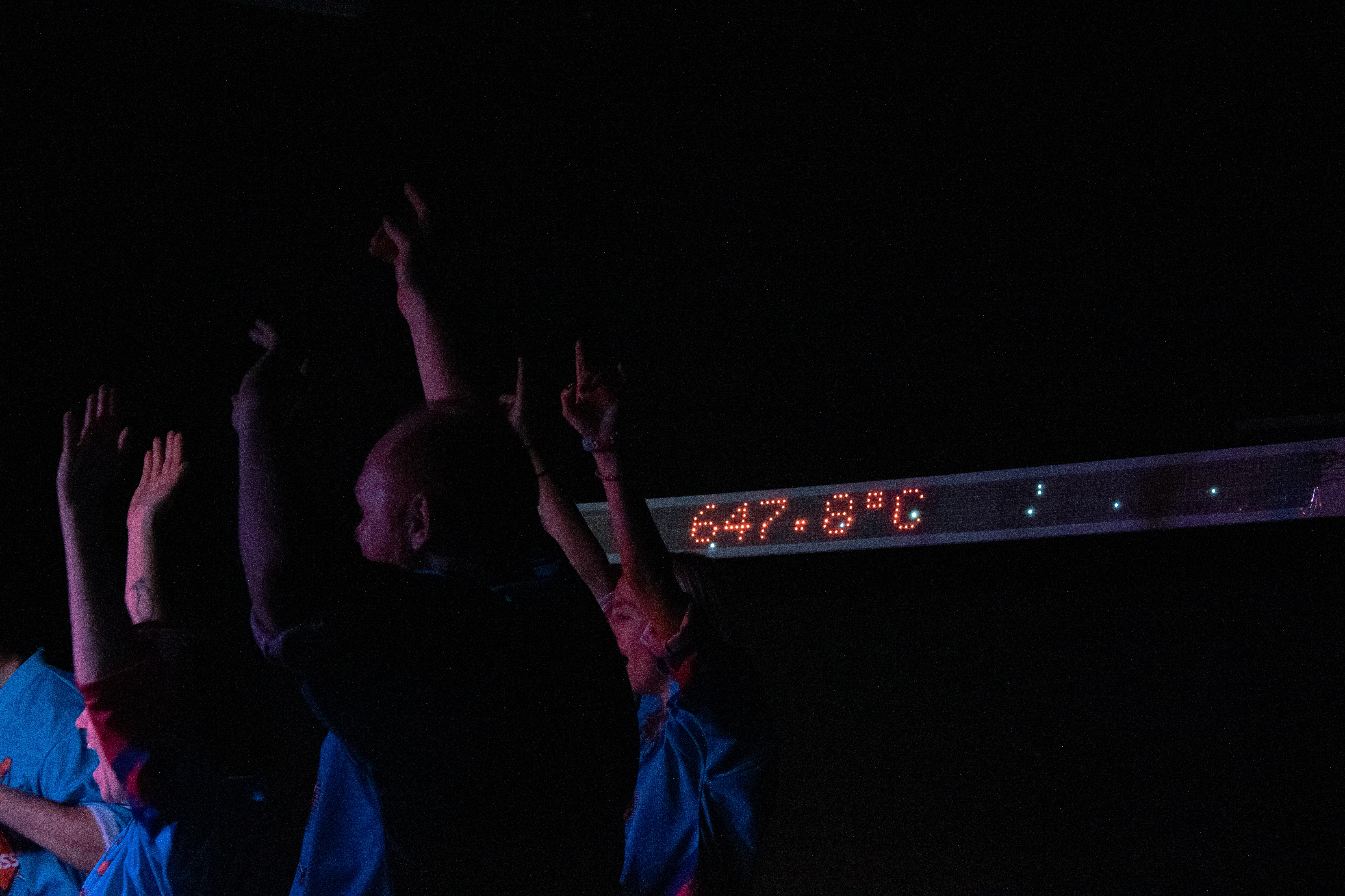
I had the chance to put this project to practice with my improv team. By aligning 8 strips of 150 LEDs and with a little programming, we put on a great show! :sunglasses:
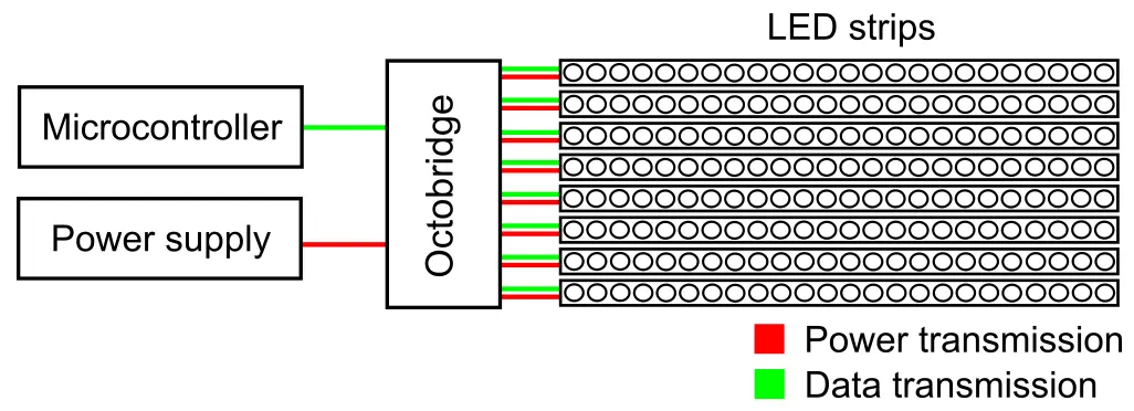
A Teensy-driven LED panel is made up of 3 main parts:
To make the bridge between these parts, and to facilitate cable work, I designed a printed circuit board I called the Octobridge. As shown in the simplified illustration below, the Octobridge receives power and data, and distributes it to the LED strips.
In practice, the power received comes from a 5V DC power supply, and data comes from a Teensy board using two CAT6 Ethernet cables. This is shown in the illustration below.
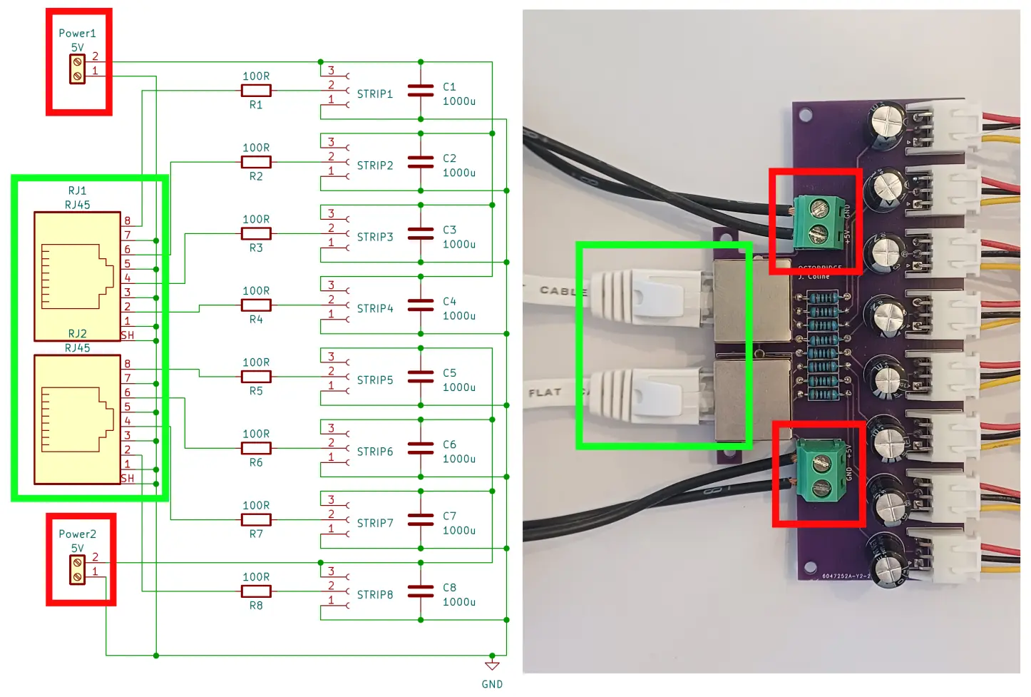
The top four LED strips are powered by the top power input and driven by the top CAT6 Ethernet cable. The bottom four LED strips are powered by the bottom power input and driven by the bottom CAT6 Ethernet cable.
The data sent to the WS2811b chips consists of a series of digital pulses, with each pulse representing a bit of information. The timing and sequence of these pulses encode the color and brightness data for each LED. Each LED interprets the data intended for it and adjusts its color and brightness accordingly.
By being individually addressable, the WS2811b LEDs can be programmed with high flexibility. Programming is particularly easy under the Arduino framework as explained in the LED programming section.
Make sure you have all the components needed. They can be ordered from the following suppliers:
Once you have gathered all the components,
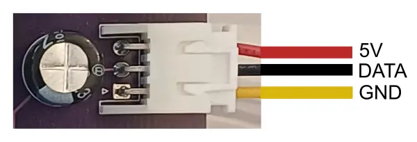
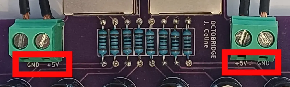
We're all set!
The last part of the project is also the most fun: you get to program your own LED animations :sunglasses:.
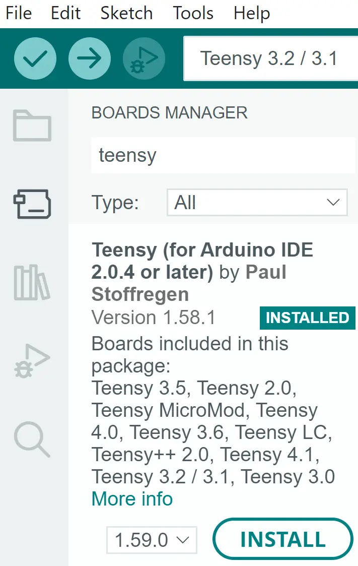
NUM_LEDS to your total number of LEDs.Finally, plug your Teensy to your computer, upload the sketch, and power up the Octobridge (after checking the wiring). Congratulations, you just brought life to your LED panel! :rocket:
You can create your own animations using the FastLED and/or the OctoWS2811 libraries. Possibilities are endless! Have fun :grinning:
Want to test an idea without wiring up hardware? You have come to the right place!
I have made available a Python script that simulates an LED panel. The downside of this simulator is that it is not using Arduino, which means you will have to re-write the program if you want to upload it to your Teensy board. However,
# Python prototyping
def scrollingTextProgram(leds):
    BLUE  = [0, 0, 255]
    RED   = [255, 0, 0]
    YELLOW = [255, 255, 0]
    PAUSE = 40 # milliseconds
    scrollText(leds, " EASY LED PANEL ", RED, BLUE, PAUSE)
    scrollText(leds, " EASY LED PANEL ", YELLOW, RED, PAUSE)
    scrollText(leds, " EASY LED PANEL ", BLUE, YELLOW, PAUSE)
}
compares to the same one written in Arduino
/*Arduino implementation*/
void loop() {
  int BLUE   = 0x0000FF;
  int RED    = 0xFF0000;
  int YELLOW = 0xFFFF00;
  int PAUSE  = 40; // milliseconds
  scrollText(" EASY LED PANEL ", 16 /*char array size*/, RED, BLUE, PAUSE);
  scrollText(" EASY LED PANEL ", 16 /*char array size*/, YELLOW, RED, PAUSE);
  scrollText(" EASY LED PANEL ", 16 /*char array size*/, BLUE, YELLOW, PAUSE);
}You will need to install Python by downloading and running their latest installer. See this repository for a complete tutorial for installing Python on common operating systems. The simulator depends on Pygame which you also need to install. This is easily done using the command
pip install pygamefrom the terminal.
Once you have installed all requirements, run the animation example script with the command
python animationExample.pyfrom the terminal. A window will pop, displaying the following LED animation:

Congratulations, you just brought life to your simulated LED panel! :rocket:
You can create your own animations using the simulator. I would recommend doing so in a new Python script of your own in the simulator directory. A great way to start would be to copy the animation example and edit it in a new file.
| Qty | Value | Footprint | References |
|---|---|---|---|
| 8 | 1000u | Capacitor_THT:C_Radial_D8.0mm_H11.5mm_P3.50mm | C1, C2, C3, C4, C5, C6, C7, C8 |
| 8 | 100R | Resistor_THT:R_Axial_DIN0207_L6.3mm_D2.5mm_P10.16mm_Horizontal | R1, R2, R3, R4, R5, R6, R7, R8 |
| 8 | ~ | Connector_JST:JST_XH_S3B-XH-A_1x03_P2.50mm_Horizontal | STRIP1, STRIP2, STRIP3, STRIP4, STRIP5, STRIP6, STRIP7, STRIP8 |
| 4 | MountingHole | MountingHole:MountingHole_2.5mm | H1, H2, H3, H4 |
| 2 | 5V | TerminalBlock_Phoenix:TerminalBlock_Phoenix_PT-1,5-2-5.0-H_1x02_P5.00mm_Horizontal | Power1, Power2 |
| 2 | RJ45 | Connector_RJ:RJ45_Amphenol_RJHSE538X | RJ1, RJ2 |
It measures 52.7 × 101.6 mm and has 2 copper layers, 1.6 mm thick.
32 parts, built around the RJ45. The full list of its parts is on this page, with links to each part's symbol and footprint where PCBKit's library has them.
From the jocobuilds/easy-led-panel repository on GitHub, at the commit this page was made from: the board is kicad/octobridge.kicad_pcb and its schematic kicad/octobridge.kicad_sch. PCBKit opens the board in the browser, with nothing to install.
Its repository publishes it under the GPL-3.0 licence: you may reuse it on that licence's terms (keep the author's notice, and for a copyleft licence share your changes alike).
UtilitechAS/amsreader-firmware
ESP8266 and ESP32 compatible firmware to read, interpret and publish data to MQTT from smart electrical meters, both DLMS and DSMR is supported

travisgoodspeed/goodfet
An embedded bus adapter for various microcontrollers and radios.


nv1t/standing-desk-interceptor
I wanted to intercept the communication between my Flexispot standing desk buttons. This is the progress on the project


Severson-Group/AMDC-Hardware
Circuit board designs for controlling advanced motor systems

mfkiwl/KiwiSDR_PCB
KiCAD PCB files for KiwiSDR project including active antenna and bias tee