2 layers68.6 × 53.3 mm

 jmohos/Octal_Motor_Controller
An 8-channel H-bridge motor driver assembly with controller, designed for parade float kinematic animation. Two units (one per side of the float) drive up to 16 geared motors to create spinning pinwheel scenes.
Octal Brushed Controller is an open-source printed circuit board by jmohos, from the jmohos/Octal_Motor_Controller repository on GitHub. It is a 6-layer board of 175 × 130 mm with 66 parts on 85 nets, routed with 264 tracks and 296 vias.
It is built around the DRV8871DDA and LM1117T-3.3. Its parts include 15 connectors, 14 capacitors, 10 ICs, 9 resistors and 1 fuse. It belongs with the RP2040 boards of this library.


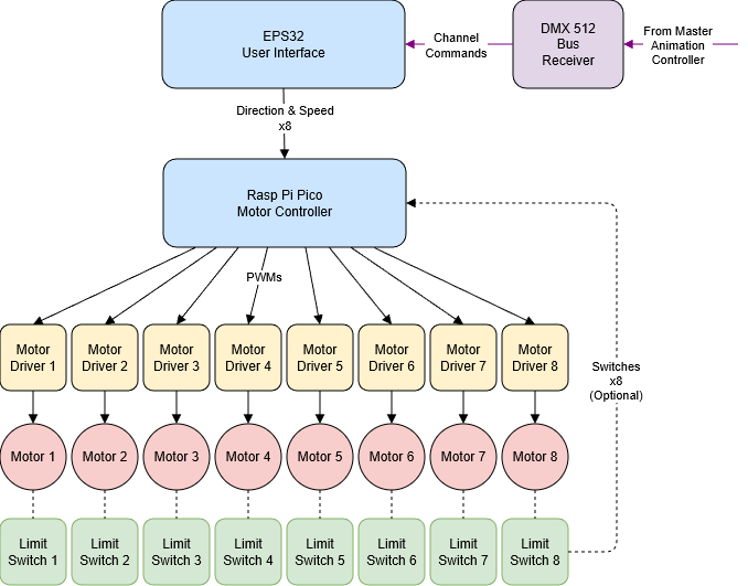
An 8-channel H-bridge motor driver assembly with controller, designed for parade float kinematic animation. Two units (one per side of the float) drive up to 16 geared motors to create spinning pinwheel scenes. Remote control is provided via the DMX 512 show control protocol.
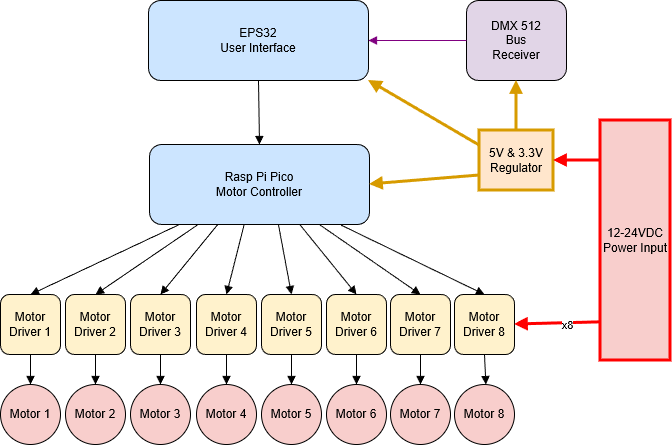
| Rail | Source | Consumers |
|---|---|---|
| 12–24 VDC | External supply | Motor drivers (DRV8871 / BTS7960) |
| 5 V | LM2596 DC:DC buck converter | ESP32 CYD display, Pico motor controller, DMX receiver |
| 3.3 V | LM1117 regulator (from 5 V) | DMX receiver, limit switch pull-ups |
An optional isolated DC:DC converter on the DMX receiver decouples local ground from the DMX bus to prevent ground shifts during high-current motor activity.
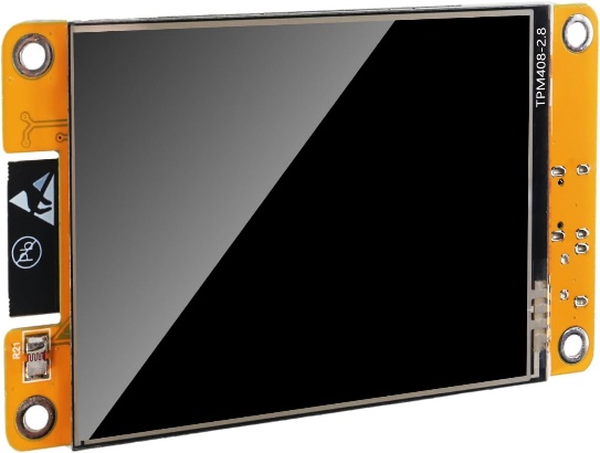
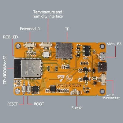
An off-the-shelf development board with a 2.8" touchscreen display.
| Front | Back |
|---|---|
 |  |
References:
Provides robust, long-range serial connection to the master animation controller.
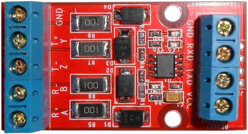
Option 1 — RS422 converter board (half-duplex) Connect R+, R−, and GND to the DMX D+, D−, and GND lines; connect GND and TXD to the CYD serial input.
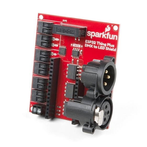
Option 2 — SparkFun DMX interface board Provides full isolation via optoisolators and an isolated DC:DC converter, protecting against voltage shifts from high-current motor activity. Wire GND, 5 V, 3.3 V, and RX pins to the CYD board.
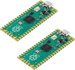
Generates PWM signals for all 8 motor drivers.
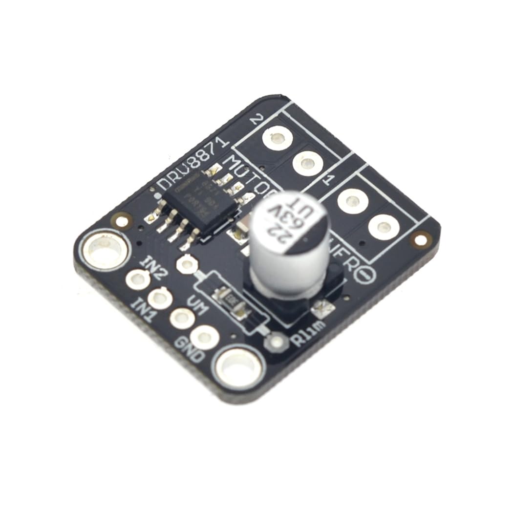
| Parameter | Value |
|---|---|
| Current limit | 2 A (30 kΩ limit resistor) |
| Input voltage | 6.5 V – 45 V |
| PWM frequency | up to 20 kHz |
| On-resistance | 565 mΩ (no heatsink needed) |
| Interface | GND + 2 PWM signals |
| Protection | Over-current, over-temp, under-voltage |
Available from Adafruit or Amazon clones. Datasheet: adafruit-drv8871-brushed-dc-motor-driver-breakout.pdf
| Parameter | Value |
|---|---|
| Current rating | up to 43 A |
| Input voltage | 6 V – 27 V |
| PWM frequency | up to 25 kHz |
| Protection | Over/under-voltage, over-current, over-temp |
| Extra requirements | 5 V for gate driver; enable pins pulled high |
Uses the same PWM signals as the DRV8871. Current monitoring pins are available. Datasheet: BTS7960-Motor-Driver.pdf
| Board | Pinout |
|---|---|
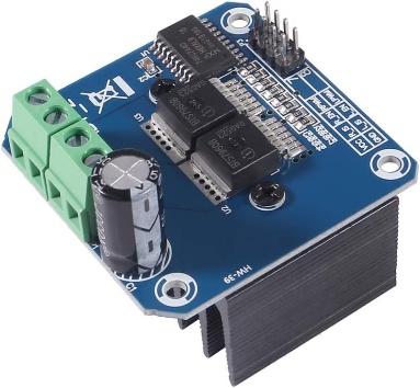 | 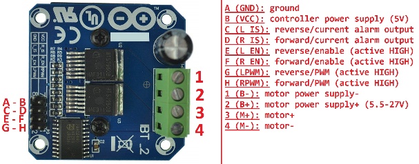 |
Custom PCB housing the Raspberry Pi Pico, DRV8871 motor driver sockets, power regulation, and all interconnects.
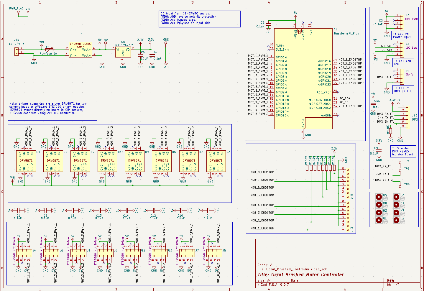
KiCad project: Hardware/Kicad/Octal_Brushed_Controller/
Both firmware projects use PlatformIO with the Arduino framework. Open each project folder in VS Code with the PlatformIO extension installed — it will auto-detect the platformio.ini and resolve dependencies.
Software/Octal_Motor_Drive_UI — User Interface Application (ESP32)Runs on the ESP32-2432S028R board. Handles:
Software/Octal_Motor_Drive_Controller — Motor Controller Application (Pico)Runs on the Raspberry Pi Pico (RP2040). Utilizes both CPU cores:
CPU0
CPU1 (watchdog)
PWM outputs run at 25 kHz to eliminate audible motor noise.
Octal_Motor_Controller/
├── README.md
├── Octal_Motor_Driver.docx          # Full design document
├── System_Diagram.drawio            # Editable system diagrams
├── System_Diagram-Top Flow.png
├── System_Diagram-Power.png
├── Hardware/
│   ├── Kicad/
│   │   └── Octal_Brushed_Controller/   # KiCad PCB project
│   └── Parts/                          # Datasheets and reference docs
└── Software/
    ├── Octal_Motor_Drive_UI/           # ESP32 UI PlatformIO project
└── Octal_Motor_Drive_Controller/ # Pico motor controller PlatformIO project| Qty | Value | Footprint | References |
|---|---|---|---|
| 13 | 0.1uF | Capacitor_THT:C_Disc_D5.1mm_W3.2mm_P5.00mm | C1, C2, C3, C4, C6, C7, C8, C9, C10, C11, C12, C13, C14 |
| 9 | 10K | Resistor_THT:R_Axial_DIN0207_L6.3mm_D2.5mm_P7.62mm_Horizontal | R1, R2, R3, R4, R5, R6, R7, R8, R9 |
| 8 | Conn_02x04_Odd_Even | Connector_IDC:IDC-Header_2x04_P2.54mm_Vertical | J4, J5, J6, J7, J8, J9, J11, J12 |
| 8 | DRV8871 | 1_Joe_Footprints:DRV8871_Brd | U1, U2, U3, U4, U6, U7, U9, U10 |
| 8 | MountingHole | MountingHole:MountingHole_3.2mm_M3 | H1, H2, H3, H4, H5, H6, H7, H8 |
| 3 | Conn_01x04 | Connector_JST:JST_PH_B4B-PH-K_1x04_P2.00mm_Vertical | J1, J2, J3 |
| 3 | TestPoint | TestPoint:TestPoint_Loop_D2.50mm_Drill1.0mm | TP1, TP2, TP4 |
| 2 | Screw_Terminal_01x08 | TerminalBlock_Phoenix:TerminalBlock_Phoenix_MPT-0,5-8-2.54_1x08_P2.54mm_Horizontal | J13, J15 |
| 1 | 10uF-T | Capacitor_THT:CP_Radial_Tantal_D5.5mm_P2.50mm | C5 |
| 1 | 12-24V in | Connector_Wire:SolderWire-2sqmm_1x02_P7.8mm_D2mm_OD3.9mm | J14 |
| 1 | 3.3V | TestPoint:TestPoint_Loop_D2.50mm_Drill1.0mm | TP7 |
| 1 | 5V | TestPoint:TestPoint_Loop_D2.50mm_Drill1.0mm | TP6 |
| 1 | DMX | Connector_JST:JST_PH_B6B-PH-K_1x06_P2.00mm_Vertical | J10 |
| 1 | DMX_RX | TestPoint:TestPoint_Loop_D2.50mm_Drill1.0mm | TP3 |
| 1 | DMX_TX | TestPoint:TestPoint_Loop_D2.50mm_Drill1.0mm | TP5 |
| 1 | GND | TestPoint:TestPoint_Loop_D2.50mm_Drill1.0mm | TP8 |
| 1 | LM1117T-3.3 | Package_TO_SOT_THT:TO-220-3_Vertical | U5 |
| 1 | Polyfuse 5A | Fuse:Fuse_Littelfuse_395Series | F1 |
| 1 | RaspberryPi_Pico | Module:RaspberryPi_Pico_Common_THT | A1 |
| 1 | ~ | 1_Joe_Footprints:DCDC_Converter_LM2596_3A | U8 |
It measures 175 × 130 mm and has 6 copper layers, 1.6 mm thick.
66 parts, built around the DRV8871DDA and LM1117T-3.3. The full list of its parts is on this page, with links to each part's symbol and footprint where PCBKit's library has them.
From the jmohos/Octal_Motor_Controller repository on GitHub, at the commit this page was made from: the board is Hardware/Kicad/Octal_Brushed_Controller/Octal_Brushed_Controller.kicad_pcb and its schematic Hardware/Kicad/Octal_Brushed_Controller/Octal_Brushed_Controller.kicad_sch. PCBKit opens the board in the browser, with nothing to install.
Its repository states no licence, so its author keeps all rights: ask jmohos before reusing the design.

DRWJSCHMIDT/T41
This is the repository for the officially released V10, V11, and V12 versions of the T41 Software Defined Transceiver hardware and kits.


ceteras/PicoLVDS
Tested with B089AW01-V.0 and HSD089IFW1-A00-V1.0 on a breadboard. I'm sure it will work with other displays from old netbooks.

