
4 layers30.7 × 34.2 mm

 jmfriedt/max2771_fx2lp67
multi MAX2771 GNSS receiver
Max2771 fx2lp with ref is an open-source printed circuit board by jmfriedt, from the jmfriedt/max2771_fx2lp repository on GitHub, published under the GPL-3.0 licence. It is a 4-layer board of 30.7 × 34.2 mm with 79 parts on 84 nets, routed with 561 tracks and 110 vias.
It is built around the MAX2771ETI+. Its parts include 32 capacitors, 26 resistors, 7 connectors, 5 ICs and 4 inductors. It belongs with the radio and wireless boards of this library.
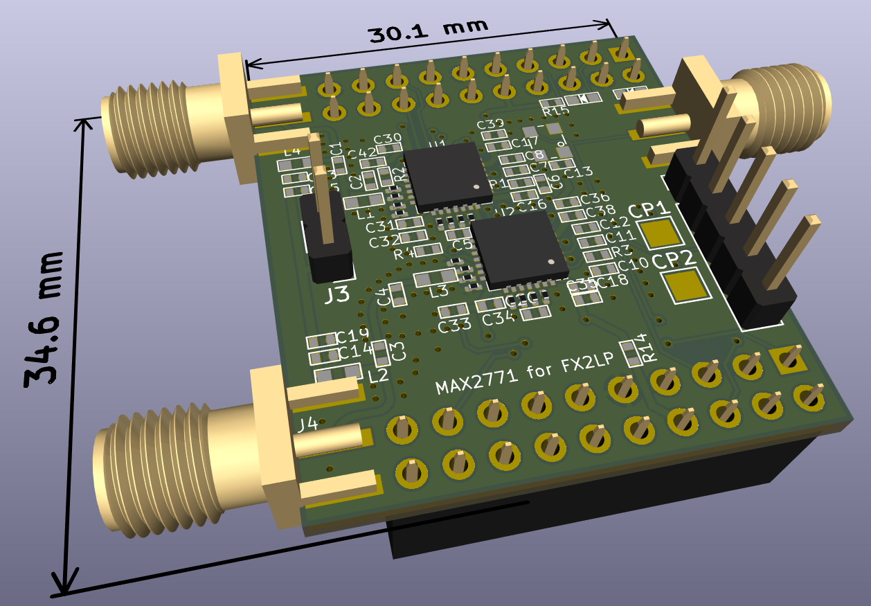
From Tomoji Takasu's Pocket SDR design, v2.3 found at https://github.com/tomojitakasu/PocketSDR, to be fitted on https://fr.aliexpress.com/item/1005006134347046.html FX2LP development board:
Schematic:
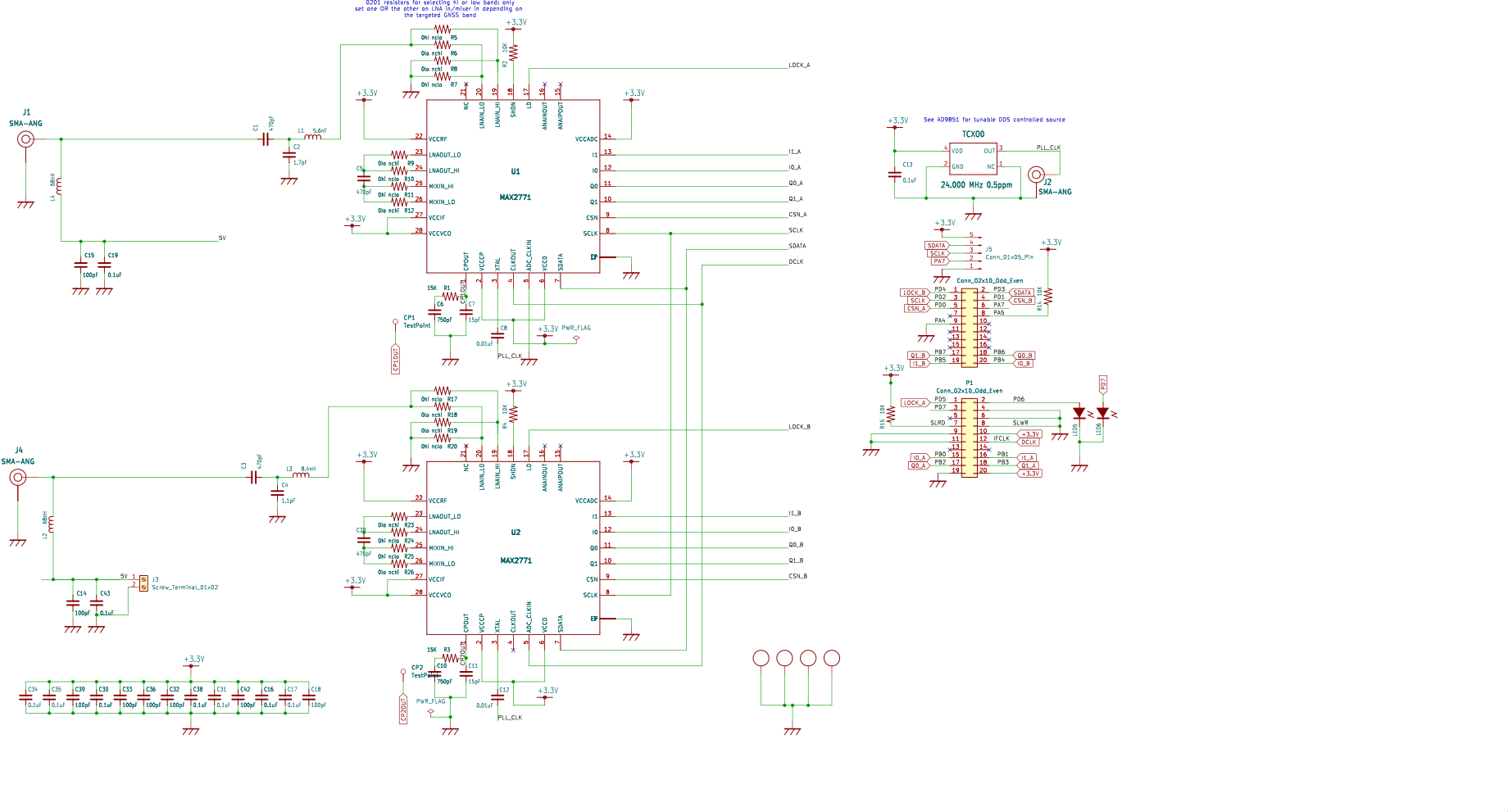
Notice that the low-pass matching filters L1/C2 and L3/C4 are fitted with 5.6 nH/1.7 pF and 8.4 nH/1.1 pF according to the typical application circuit found on page 49 of the datasheet. The values are selected for the upper and lower L-band respectively. If both MAX2771 are to be used in the same band, e.g. for CRPA, then replace the L/C values with the values best suited for the targeted band.
Board layers (4-layer circuit to match the 50-ohm transmission lines in the L-band):
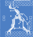
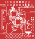
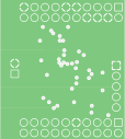
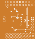
Use the interactive BOM (in the bom/ subdirectory) when assembling the board.
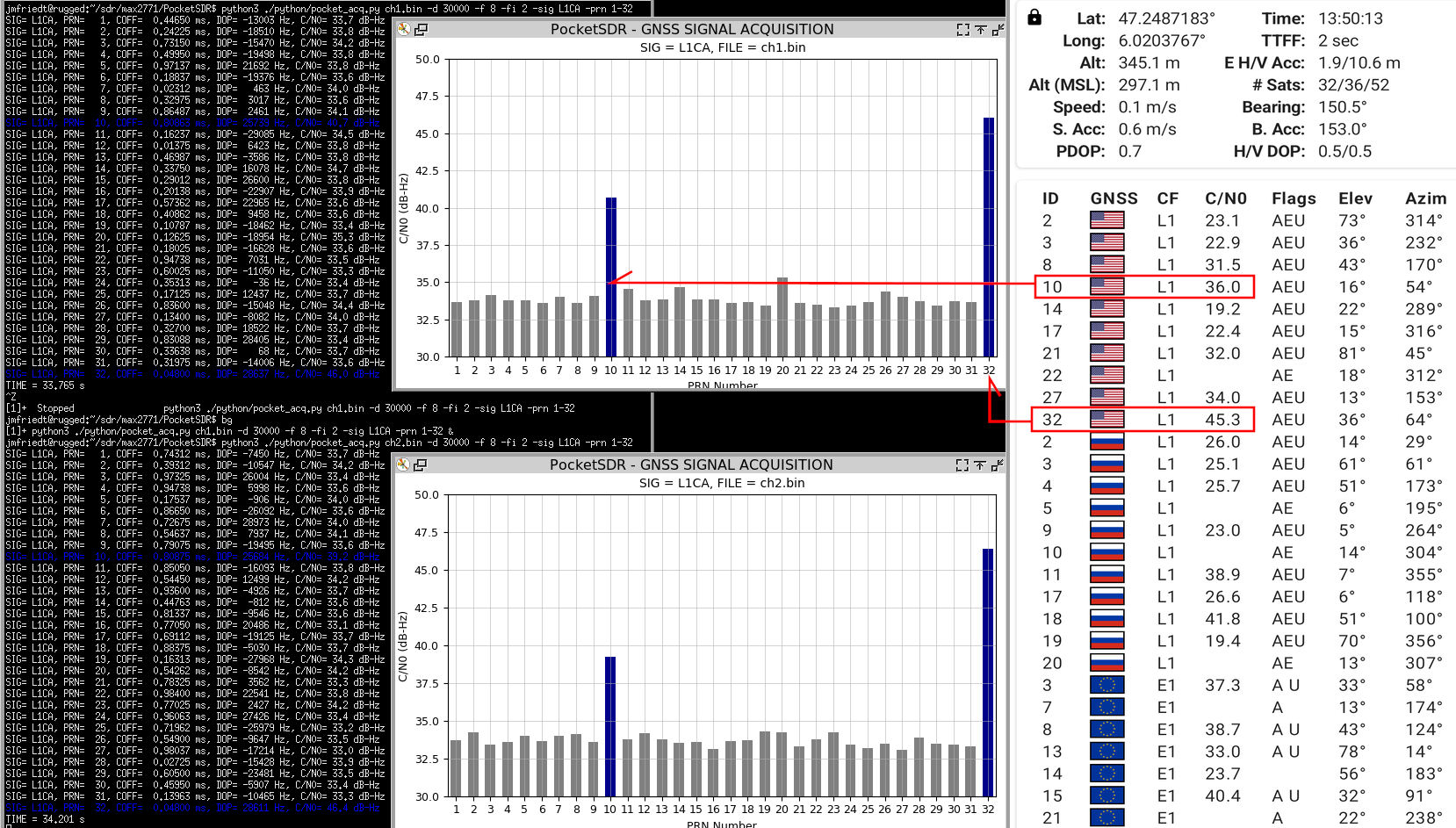
Result of the assembled board: configuring both MAX2771 to collect the upper (L1) band with 8 MHz sampling rate and 2 MHz IF bandwith
sudo ./app/pocket_conf/pocket_conf conf/pocket_L1L1_8MHz.confand recording using
sudo ./app/pocket_dump/pocket_dump -t 5 ch1.bin ch2.binThe two binary files are processed for acquisition of GPS L1 C/A signal with
python3 ./python/pocket_acq.py ch2.bin -d 30000 -f 8 -fi 2 -sig L1CA -prn 1-32with the -d option to reach Doppler shifts up to 30 kHz to account for
the poor quality TCXO whereas the default is to search for 5 kHz (theoretical
Doppler shift maximum assuming a perfect reference clock, e.g. Rb, Cs or HM
source or good quality OCXO).
First demonstration, Doppler limited to 30 kHz offset from carrier:
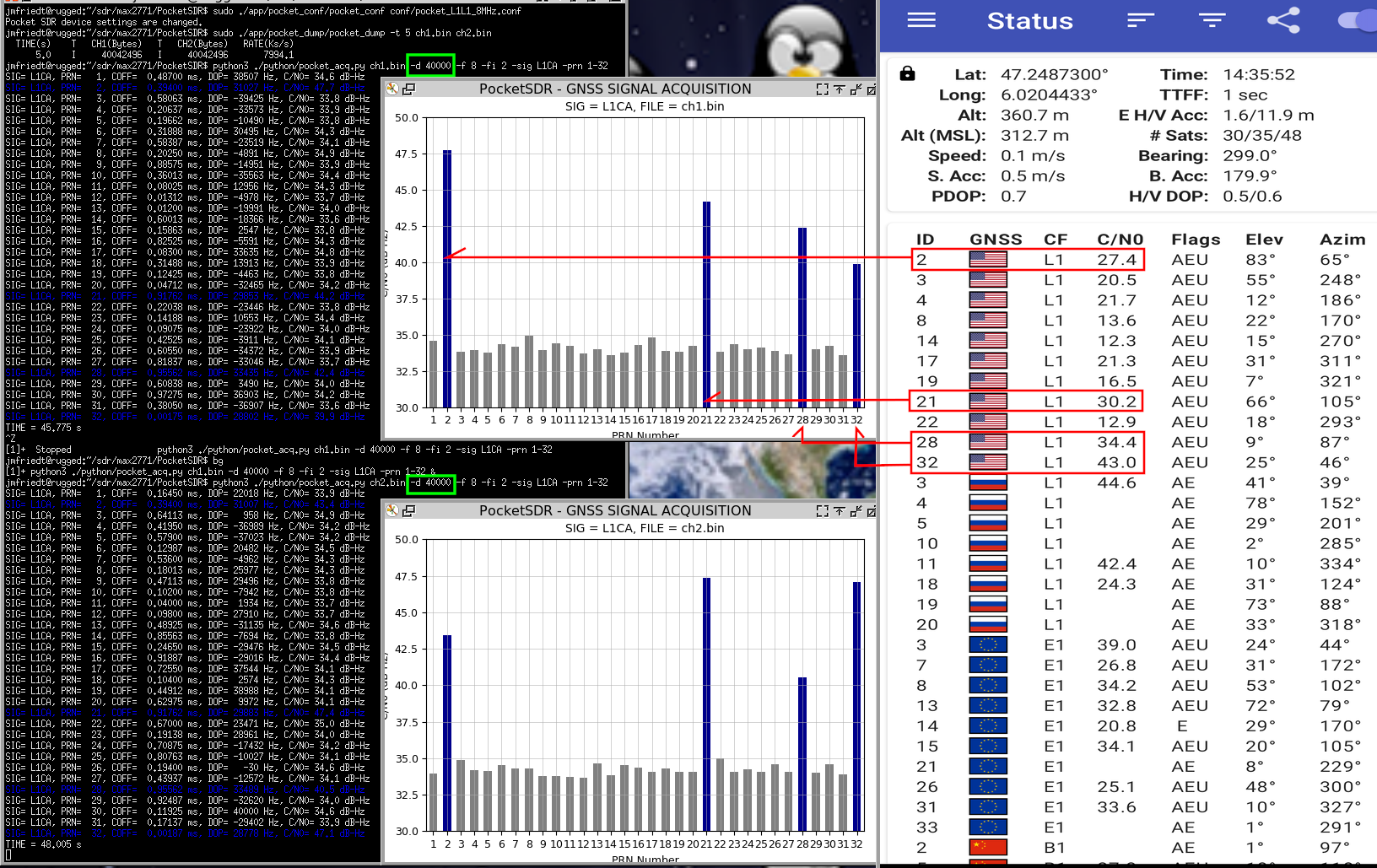
Second demonstration, Doppler extended to 40 kHz offset from carrier matching the mobile phone measurements:
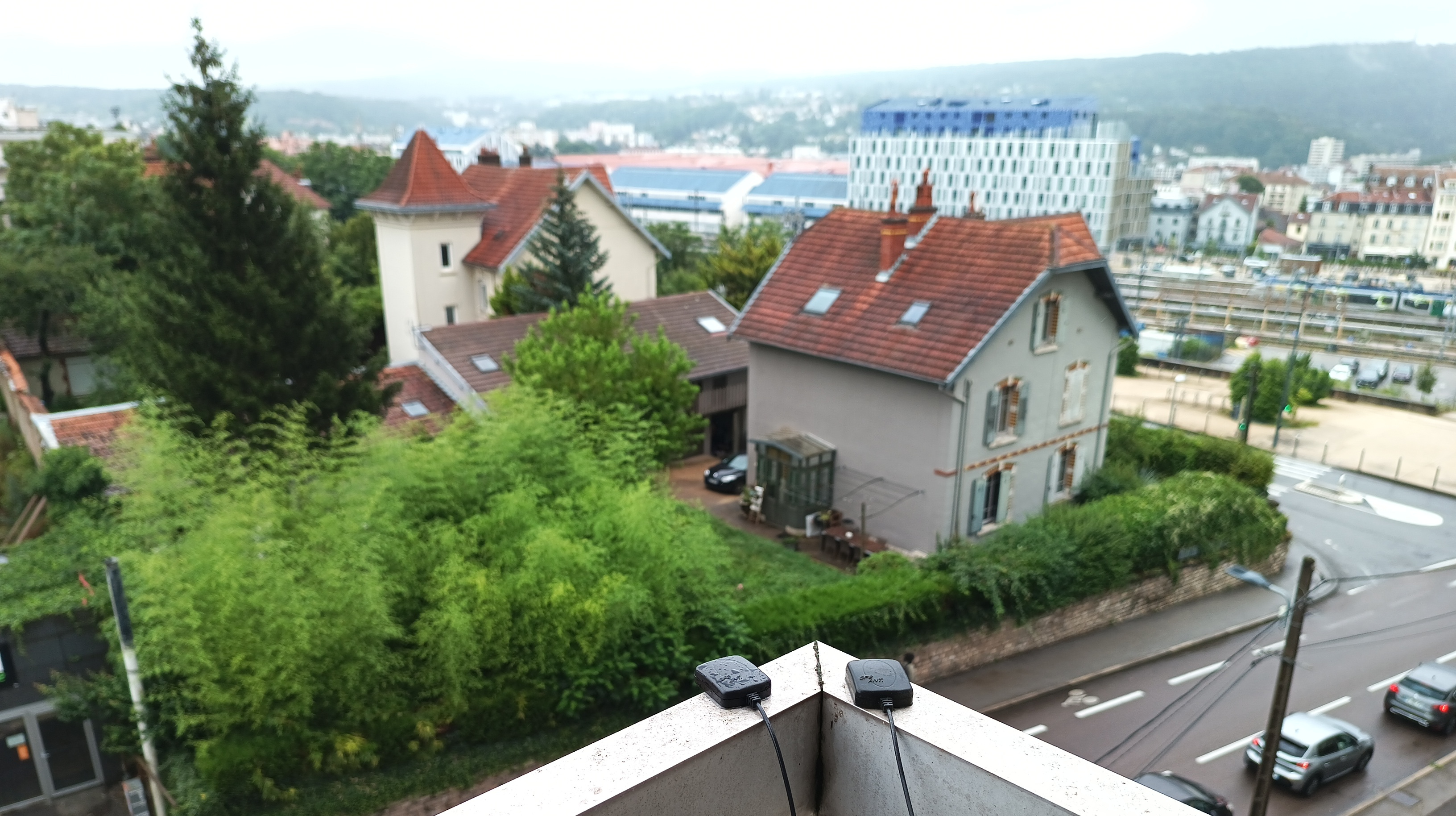
Experimental setup:
| Qty | Value | Footprint | References |
|---|---|---|---|
| 10 | 0.1uF | pocket_sdr_v2.3:C1005 | C13, C16, C17, C19, C30, C31, C34, C35, C38, C43 |
| 8 | 0hi nclo | Resistor_SMD:R_0201_0603Metric | R5, R7, R10, R11, R17, R20, R24, R25 |
| 8 | 0lo nchi | Resistor_SMD:R_0201_0603Metric | R6, R8, R9, R12, R18, R19, R23, R26 |
| 8 | 100pF | pocket_sdr_v2.3:C1005 | C14, C15, C18, C32, C33, C36, C39, C42 |
| 4 | 10k | pocket_sdr_v2.3:C1005 | R2, R4, R14, R15 |
| 4 | 10k | Resistor_SMD:R_0402_1005Metric_Pad0.72x0.64mm_HandSolder | R13, R16, R21, R22 |
| 4 | 470pF | pocket_sdr_v2.3:C1005 | C1, C3, C5, C20 |
| 3 | SMA-ANG | pocket_sdr_v2.3:SMA-ANG | J1, J2, J4 |
| 2 | 0.01uF | pocket_sdr_v2.3:C1005 | C8, C12 |
| 2 | 15K | pocket_sdr_v2.3:C1005 | R1, R3 |
| 2 | 15pF | pocket_sdr_v2.3:C1005 | C7, C11 |
| 2 | 1n | Capacitor_SMD:C_0402_1005Metric_Pad0.74x0.62mm_HandSolder | C9, C21 |
| 2 | 68nH | pocket_sdr_v2.3:C1608 | L2, L4 |
| 2 | 750pF | pocket_sdr_v2.3:C1005 | C6, C10 |
| 2 | Conn_02x10_Odd_Even | Connector_PinSocket_2.54mm:PinSocket_2x10_P2.54mm_Vertical | P1, P2 |
| 2 | LED1608 | pocket_sdr_v2.3:LED_1608 | LED5, LED6 |
| 2 | MAX2771 | pocket_sdr_v2.3:TQFN28 | U1, U2 |
| 2 | TestPoint | TestPoint:TestPoint_Pad_2.0x2.0mm | CP1, CP2 |
| 2 | ~ | ref_osc:spdt | U3, U5 |
| 1 | 1.1pF | pocket_sdr_v2.3:C1005 | C4 |
| 1 | 1.7pF | pocket_sdr_v2.3:C1005 | C2 |
| 1 | 24.000 MHz 0.5ppm | pocket_sdr_v2.3:TCXO | TCXO0 |
| 1 | 5.6nF | pocket_sdr_v2.3:C1608 | L1 |
| 1 | 8.4nH | pocket_sdr_v2.3:C1608 | L3 |
| 1 | Conn_01x05_Pin | Connector_PinHeader_2.54mm:PinHeader_1x05_P2.54mm_Vertical | J5 |
| 1 | Screw_Terminal_01x02 | Connector_PinHeader_2.54mm:PinHeader_1x02_P2.54mm_Vertical | J3 |
| 1 | ~ | reference_oscillator:8-LGA | U4 |

oresat/oresat-gps-hardware
Hardware for OreSat's SDR GPS receive and other SDR GPS projects

osqzss/PocketSDR
The Pocket SDR FE device includes 2, 4, or 8 RF frontend channels, supporting the GNSS L1 band (1525 - 1610 MHz) or L2/L5/L6 bands (1160 - 1290 MHz). For these signal bands, refer to GNSS Signal Bands.


horychen/ProjectEureka
12 phase motor drive including inverter, microcontroller-mother-board, sensing, communication, DAC, etc.


It measures 30.7 × 34.2 mm and has 4 copper layers, 1.6 mm thick.
79 parts, built around the MAX2771ETI+. The full list of its parts is on this page, with links to each part's symbol and footprint where PCBKit's library has them.
From the jmfriedt/max2771_fx2lp repository on GitHub, at the commit this page was made from: the board is HW/max2771_fx2lp_with_ref.kicad_pcb and its schematic HW/max2771_fx2lp.kicad_sch. PCBKit opens the board in the browser, with nothing to install.
Its repository publishes it under the GPL-3.0 licence: you may reuse it on that licence's terms (keep the author's notice, and for a copyleft licence share your changes alike).