
2 layers100 × 100 mm
RC PT1
jkordek1/Automatic-Control
A collection of educational printed circuit boards (PCBs) developed for laboratory exercises in Automatic Control Systems.
12 parts
 jkordek1/Automatic-Control
A collection of educational printed circuit boards (PCBs) developed for laboratory exercises in Automatic Control Systems.
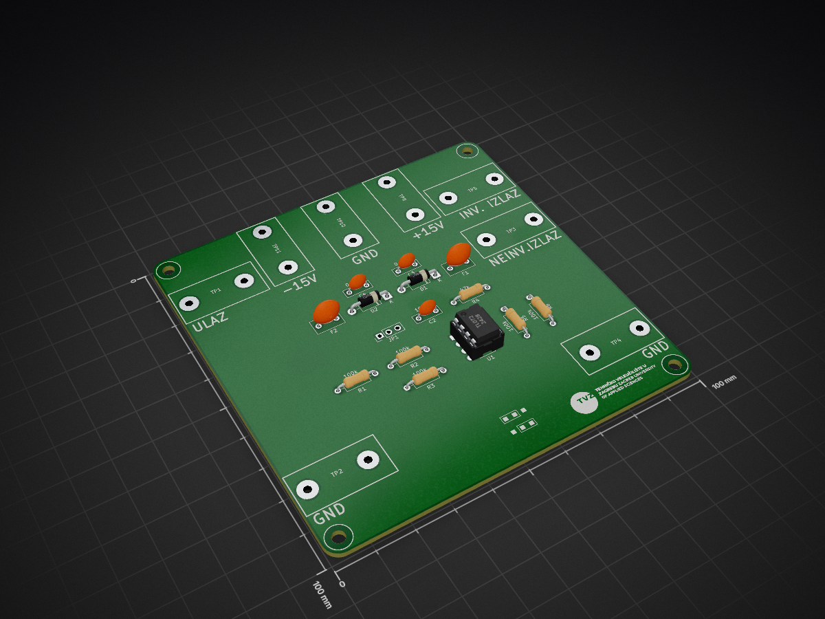
Active PI is an open-source printed circuit board by jkordek1, from the jkordek1/Automatic-Control repository on GitHub. It is a 2-layer board of 100 × 100 mm with 29 parts on 13 nets, routed with 72 tracks and 0 vias.
It is built around the TL072. Its parts include 6 resistors, 3 capacitors, 2 diodes, 2 fuses and 1 IC.
A collection of educational printed circuit boards (PCBs) developed for laboratory exercises in Automatic Control Systems. The project demonstrates the implementation of fundamental analog transfer functions using passive components and operational amplifiers.
The boards are intended for university courses and provide a hands-on platform for studying the behavior of basic dynamic systems through practical experiments.
This repository contains three independent laboratory boards:
| Board | Description |
|---|---|
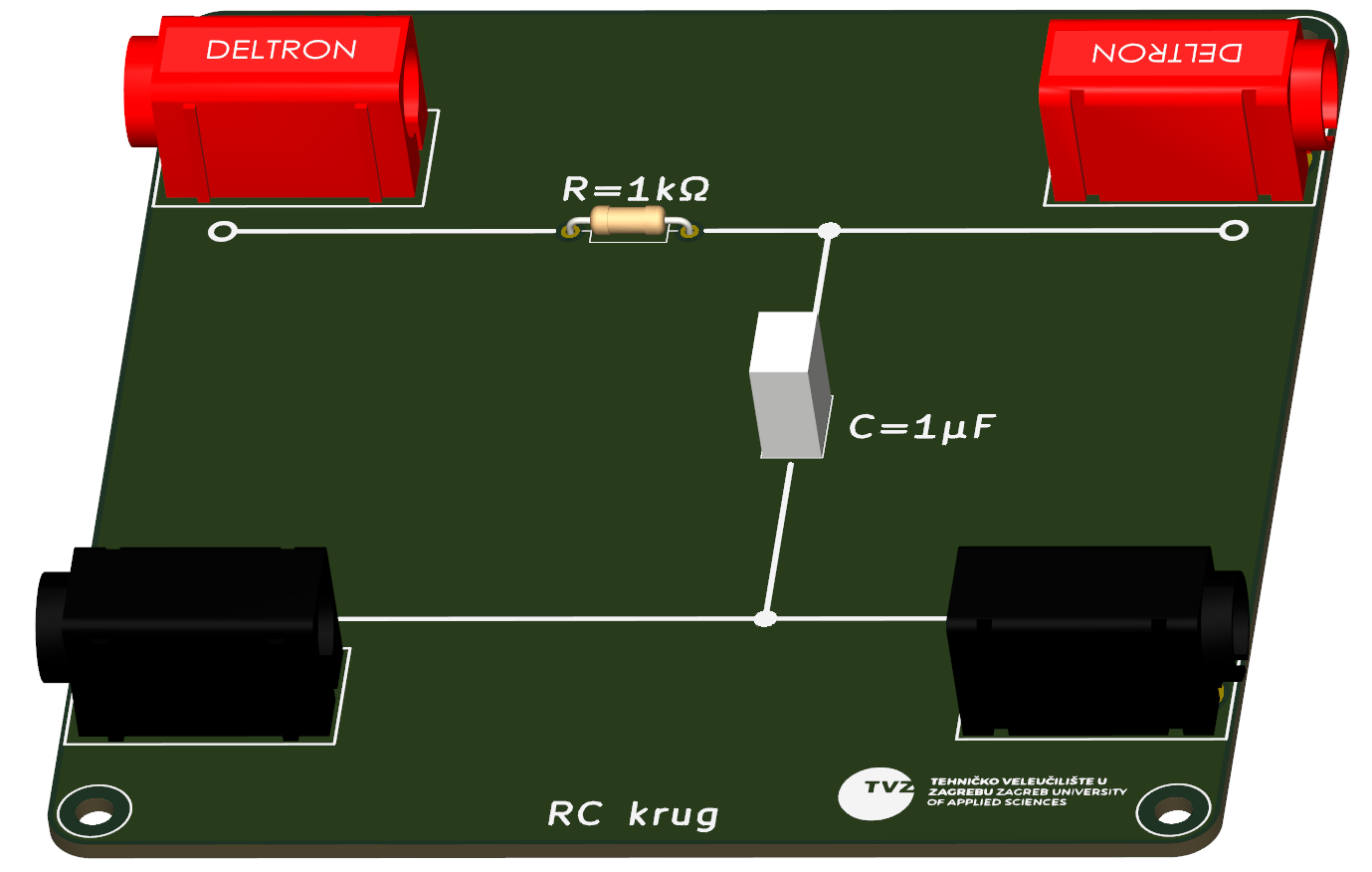
| RC Network | Passive first-order RC circuit for studying time constants, transient response, and frequency response. |
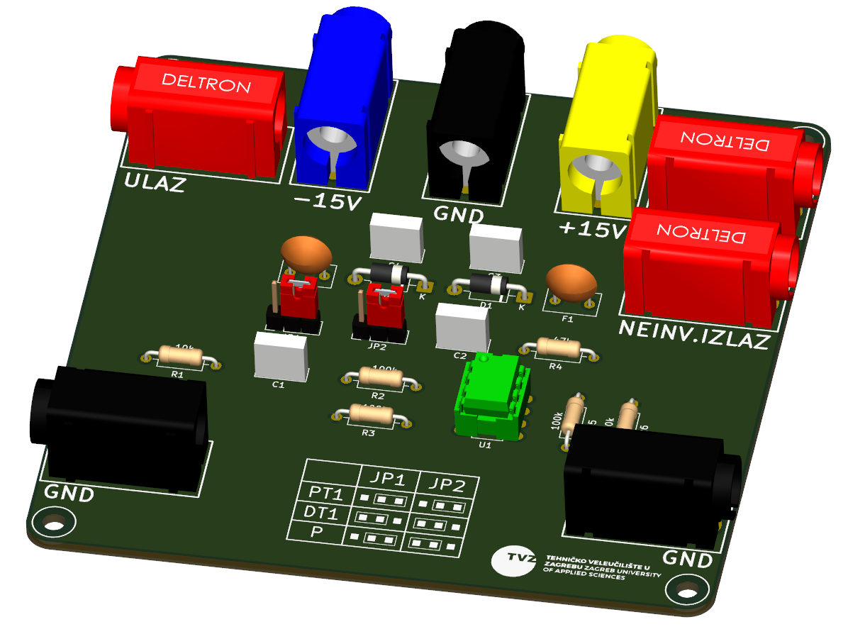
| P / PT1 / DT1 | Active analog circuit implementing proportional (P), first-order lag (PT1), and derivative (DT1) transfer functions using operational amplifiers. |
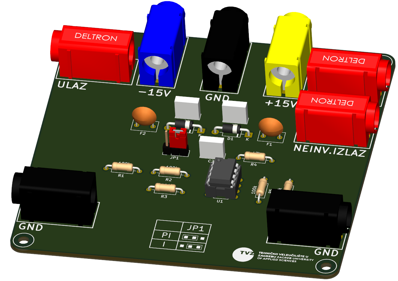
| PI / I Controller | Active analog circuit implementing an integrator (I) and proportional-integral (PI) controller. |
A passive first-order RC circuit used to investigate:
An operational amplifier based circuit providing three selectable transfer functions:
Jumper Configuration:
| Transfer Function | JP1 | JP2 |
|---|---|---|
| PT1 | Pins 2–3 | Pins 2–3 |
| DT1 | Pins 1–2 | Pins 1–2 |
| P | Pins 2–3 | Pins 1–2 |
This board allows students to compare the behavior of different dynamic systems under identical experimental conditions.
An operational amplifier implementation of:
Jumper Configuration:
| Transfer Function | JP1 |
|---|---|
| PI | 1–2 |
| I | 2–3 |
The board is intended for experiments involving closed-loop control and controller tuning.
Designed using KiCad.
The repository includes:
These boards are suitable for:
Planned additions include:
This project is released under the MIT License.
Designed and developed for educational use in Automatic Control Systems laboratories.
| Qty | Value | Footprint | References |
|---|---|---|---|
| 5 | 100k | Resistor_THT:R_Axial_DIN0207_L6.3mm_D2.5mm_P10.16mm_Horizontal | R1, R2, R3, R4, R5 |
| 4 | MountingHole | MountingHole:MountingHole_3.2mm_M3 | H1, H2, H3, H4 |
| 3 | TestPoint | Library:DELTRON 4mm banana socket - red | TP1, TP3, TP5 |
| 3 | TestPoint | Library:DELTRON 4mm banana socket - black | TP2, TP4, TP10 |
| 2 | 0.1uF | Capacitor_THT:C_Rect_L7.2mm_W2.5mm_P5.00mm | C3, C4 |
| 2 | 100mA | Capacitor_THT:C_Disc_D7.5mm_W4.4mm_P5.00mm | F1, F2 |
| 2 | 1N4007 | Diode_THT:D_DO-41_SOD81_P10.16mm_Horizontal | D1, D2 |
| 1 | 10nF | Capacitor_THT:C_Rect_L7.2mm_W2.5mm_P5.00mm | C2 |
| 1 | 47k | Resistor_THT:R_Axial_DIN0207_L6.3mm_D2.5mm_P10.16mm_Horizontal | R6 |
| 1 | Jumper_3_Open | Library:Jumper_1x03 | JP1 |
| 1 | LOGO | Library:tvz | G*** |
| 1 | LOGO | Library:logo | G*** |
| 1 | TL072 | Package_DIP:DIP-8_W7.62mm_LongPads | U1 |
| 1 | TestPoint | Library:DELTRON 4mm banana socket - yellow | TP9 |
| 1 | TestPoint | Library:DELTRON 4mm banana socket - blue | TP11 |
jkordek1/Automatic-Control
A collection of educational printed circuit boards (PCBs) developed for laboratory exercises in Automatic Control Systems.

ohmtech-rdi/eurorack-blocks
Software to Hardware Prototyping for Eurorack using C++, Max/Gen~ or Faust

ctag-fh-kiel/ctag-tbd
CTAG TBD >>to be determined<< an extendible open source Eurorack sound module

plinkysynth/plinky_public
a public release of the plinky sw and hw


matthewcieplak/super-sixteen
Code and schematics for the Super Sixteen Eurorack sequencer

mzuelch/CATs-Eurosynth
Analog Synth Eurorack Modules

StoneRose35/cortexguitarfx
guitar effects processor implemented on various arm cortex platforms
It measures 100 × 100 mm and has 2 copper layers, 1.6 mm thick.
29 parts, built around the TL072. The full list of its parts is on this page, with links to each part's symbol and footprint where PCBKit's library has them.
From the jkordek1/Automatic-Control repository on GitHub, at the commit this page was made from: the board is Active-PI/Active-PI.kicad_pcb and its schematic Active-PI/Active-PI.kicad_sch. PCBKit opens the board in the browser, with nothing to install.
Its repository states no licence, so its author keeps all rights: ask jkordek1 before reusing the design.