2 layers98 × 79.5 mm
Esp32 example
rharpalani/InventoryIQ
An ESP32 microcontroller-based inventory management solution for the computer engineering lab.
35 parts

 JJ1553/ECE445-Oscillosketch
This repo serves as a Lab Notebook for The Oscillosketch project for ECE 445 senior design managed by Eric Vo and Josh Jenks
OscilloSketch is an open-source printed circuit board by JJ1553, from the JJ1553/ECE445-Oscillosketch repository on GitHub. It is a 2-layer board of 98.9 × 83.2 mm with 130 parts on 89 nets, routed with 489 tracks and 78 vias.
It is built around the ESP32-S3-WROOM-1-N8, OPA2192QDGKRQ1 and SN74LV1T34DCK, with the AZ1117CD-3.3TRG1, PEC11R-4220F-S0024 and SP0503BAHTG among its other parts. Its parts include 40 resistors, 29 capacitors, 13 diodes, 8 connectors and 8 switches. It belongs with the ESP32 boards of this library.


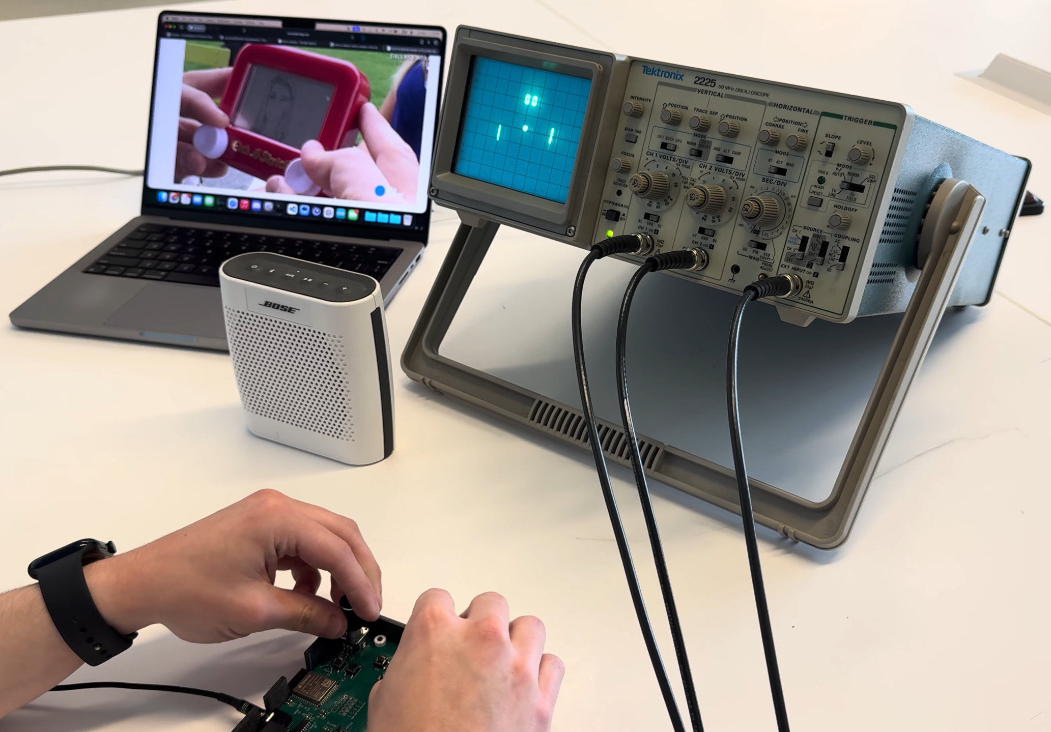
OscilloSketch is a handheld embedded system that turns a standard oscilloscope operating in XY mode into an interactive vector display.
Developed for ECE 445: Senior Design at the University of Illinois Urbana-Champaign, the project uses an ESP32-S3, dual 12-bit DAC, precision analog output stage, rotary encoders, and custom firmware to generate synchronized X/Y analog signals for drawing, vector graphics, gameplay, and audio visualization.
The final system is powered entirely over USB-C, produces approximately ±5 V X/Y outputs, and updates coordinated X/Y points at approximately 110 kHz.
Team 22 — Spring 2026
Josh Jenks · Eric Vo
🏆 Inducted into the ECE 445 Hall of Fame — an honor awarded to 10 teams out of approximately 100 projects (top 10%).
Watch the final project demo on YouTube →
Etch-a-Sketch drawing, vector graphics, Pong, audio visualization, and real-time filtering on an analog oscilloscope.
OscilloSketch supports four primary operating modes:
The firmware also supports Z-axis blanking to suppress visible retrace lines between disconnected vector primitives on compatible oscilloscopes.
At a high level:
Rotary Encoders / Buttons
           │
           ▼
      ESP32-S3
           │
       20 MHz SPI
           │
           ▼
     MCP4922 DAC
       RAW X / Y
        0–3.3 V
           │
           ▼
 Precision Analog Stage
           │
      ~−5 V to +5 V
        ┌──┴──┐
        ▼     ▼
      BNC X  BNC Y
        │     │
        └──┬──┘
           ▼
      Oscilloscope
         XY Mode
The hardware is powered from a single 5 V USB-C input. An AZ1117C generates the 3.3 V digital rail, while an LM27762 charge pump generates the approximately ±5 V analog rails used by the output stage.
A key challenge was maintaining enough replay bandwidth for drawings to remain visually persistent on an analog oscilloscope.
The final firmware separates application logic from the timing-critical output path:
Input / Mode Logic
        │
        ▼
Coordinate Generation
        │
        ▼
Shared Replay Engine
        │
        ▼
Dedicated Replay Task
        │
        ▼
SPI DAC Writes + LDAC
        │
        ▼
~110 kHz X/Y Output
The main application loop handles user input, mode switching, game logic, and drawing updates. A separate FreeRTOS replay task continuously outputs synchronized X/Y coordinates to the DAC.
This architecture evolved from earlier software-timer and hardware-timer implementations that were limited to substantially lower practical refresh rates. The final dual-core design reached a stable operating rate of approximately 110 kHz, exceeding the original 10 kHz requirement by roughly 11×.
Major components include:
| Subsystem | Component |
|---|---|
| MCU | ESP32-S3-WROOM-1-N16 |
| DAC | MCP4922 dual 12-bit SPI DAC |
| Analog output | OPA2192 |
| Reference buffer | TLV9061 |
| Bipolar supply | LM27762 |
| 3.3 V regulator | AZ1117C |
| User input | 2× PEC11R rotary encoders + 4 pushbuttons |
| Power | 5 V USB-C |
| X/Y output | BNC |
| Audio output | 3.5 mm stereo |
| Z-blanking | 5 V level-shifted BNC output |
The PCB is approximately 98.5 mm × 83 mm and is mounted in a custom 3D-printed enclosure with an acrylic top panel.
The completed system met its primary design requirements.
| Parameter | Measured Result |
|---|---|
| X/Y resolution | 12 bit |
| Coordinated update rate | 110 kHz |
| SPI clock | 20 MHz |
| USB input current | ~98 mA |
| Input-to-output latency | ~19.2 ms |
| Final X/Y output range | ~−4.88 V to +4.99 V |
| Analog step size | 2.41 mV/code |
| X/Y update mismatch | ~560 ns |
The original goal was to stream audio from a host computer over USB. Several versions of the serial transport were developed using buffering, sequence tracking, retries, CRC checking, and playback telemetry.
Although the direct audio playback path produced clean output, the live transport remained susceptible to packet loss and start/stop behavior. For the final demonstration, the audio was therefore converted offline to 16-bit PCM and stored directly in ESP32 flash.
The repository includes make_embedded_song.py for generating the embedded audio header.
Example:
python make_embedded_song.py "/path/to/song.mp3" --seconds 30 --rate 16000 --channels 2FFmpeg and pydub are required for conversion.
This repository contains the final project deliverables:
/
├── firmware/          Final ESP32-S3 firmware
├── lab-notebooks/     Engineering development logs
├── final-report/      ECE 445 final technical report
├── assets/            README media
└── README.md
The final report contains the complete hardware design, calculations, schematics, requirements, verification procedures, and measured results.
The lab notebooks document the development process, including PCB bring-up, firmware architecture changes, debugging, timing measurements, audio experiments, and final system integration.
The firmware targets the ESP32-S3-WROOM-1-N16 using the Arduino ESP32 environment.
Typical setup:
Oscillosketch.ino over USB-C.Because the final firmware embeds audio in flash, a larger application partition such as Huge APP may be required.
The project was designed around four primary requirements:
All four primary requirements were met by the completed system.
For full technical details, see:
Josh Jenks
Eric Vo
ECE 445 — Senior Design
University of Illinois Urbana-Champaign
Spring 2026
| Qty | Value | Footprint | References |
|---|---|---|---|
| 13 | 10k | Resistor_SMD:R_0603_1608Metric | R1, R2, R13, R20, R21, R22, R23, R24, R25, R26, R27, R28, R29 |
| 6 | 0.01uF | Capacitor_SMD:C_0603_1608Metric | C14, C16, C17, C18, C19, C20 |
| 6 | 1uF | Capacitor_SMD:C_0603_1608Metric | C2, C7, C22, C26, C27, C29 |
| 6 | SW_Push | Button_Switch_SMD:SW_SPST_PTS645 | SW1, SW2, SW3, SW4, SW5, SW6 |
| 5 | 0.1uF | Capacitor_SMD:C_0603_1608Metric | C11, C13, C21, C25, C28 |
| 5 | 330 | Resistor_SMD:R_0603_1608Metric | R31, R32, R33, R34, R35 |
| 5 | LED | LED_SMD:LED_0805_2012Metric_Pad1.15x1.40mm_HandSolder | D2, D3, D4, D5, D6 |
| 4 | 10k | Resistor_SMD:R_0805_2012Metric | R36, R37, R38, R39 |
| 4 | 10uF | Capacitor_SMD:C_0603_1608Metric | C3, C12, C15, C23 |
| 4 | MountingHole | MountingHole:MountingHole_3.2mm_M3 | H1, H2, H3, H4 |
| 3 | 2.2uF | Capacitor_SMD:C_0603_1608Metric | C6, C8, C9 |
| 3 | 220 | Resistor_SMD:R_0603_1608Metric | R18, R19, R40 |
| 3 | BNC | Library_oscillo:LINX_CONBNC002 | J2, J3, J8 |
| 3 | D_Schottky | Diode_SMD:D_SMA | D9, D10, D11 |
| 3 | D_TVS | Diode_SMD:D_SOD-882 | D1, D8, D13 |
| 2 | 100 | Resistor_SMD:R_0603_1608Metric | R5, R30 |
| 2 | 100k | Resistor_SMD:R_0603_1608Metric | R10, R11 |
| 2 | 19.8k | Resistor_SMD:R_0603_1608Metric | R15, R17 |
| 2 | 22 | Resistor_SMD:R_0603_1608Metric | R3, R4 |
| 2 | 22uF | Capacitor_SMD:C_0805_2012Metric | C1, C24 |
| 2 | 5.1k | Resistor_SMD:R_0805_2012Metric | R6, R7 |
| 2 | 9.76k | Resistor_SMD:R_0603_1608Metric | R14, R16 |
| 2 | NC | Capacitor_SMD:C_0603_1608Metric | C4, C5 |
| 2 | PEC11R-4220F-S0024 | Library_oscillo:XDCR_PEC11R-4220F-S0024 | S1, S2 |
| 1 | +3.3V | TestPoint:TestPoint_Pad_D1.0mm | TP14 |
| 1 | +5V | TestPoint:TestPoint_Pad_D1.0mm | TP13 |
| 1 | +5VA | TestPoint:TestPoint_Pad_D1.0mm | TP18 |
| 1 | -5VA | TestPoint:TestPoint_Pad_D1.0mm | TP19 |
| 1 | 2.46V | TestPoint:TestPoint_Pad_D1.0mm | TP17 |
| 1 | 282837-3 | Library_oscillo:TE_282837-3 | J5 |
| 1 | 3.4k | Resistor_SMD:R_0603_1608Metric | R12 |
| 1 | 302k | Resistor_SMD:R_0603_1608Metric | R9 |
| 1 | 309k | Resistor_SMD:R_0603_1608Metric | R8 |
| 1 | 4.7uF | Capacitor_SMD:C_0603_1608Metric | C10 |
| 1 | AZ1117CD-3.3TRG1 | Library_oscillo:TO252-2-3.3V_DIO | U2 |
| 1 | AudioJack3 | Connector_Audio:Jack_3.5mm_CUI_SJ1-3523N_Horizontal | J7 |
| 1 | Conn_01x03_Pin | Connector_PinHeader_2.54mm:PinHeader_1x03_P2.54mm_Vertical | J6 |
| 1 | Conn_01x05_Pin | Connector_PinHeader_2.54mm:PinHeader_1x05_P2.54mm_Vertical | J4 |
| 1 | ESP32-S3-WROOM-1 | RF_Module:ESP32-S3-WROOM-1 | U1 |
| 1 | LDAC | TestPoint:TestPoint_Pad_D1.0mm | TP12 |
| 1 | LEFT_A | TestPoint:TestPoint_Pad_D1.0mm | TP4 |
| 1 | LEFT_B | TestPoint:TestPoint_Pad_D1.0mm | TP3 |
| 1 | LM27762DSST | Library_oscillo:IC_LM27762DSST | U3 |
| 1 | MCP4922-E_SL | Library_oscillo:MCP4922 | U4 |
| 1 | OPA2192QDGKRQ1 | Library_oscillo:OPA219 | U5 |
| 1 | OUT_X | TestPoint:TestPoint_Pad_D1.0mm | TP15 |
| 1 | OUT_Y | TestPoint:TestPoint_Pad_D1.0mm | TP16 |
| 1 | OUT_Z | TestPoint:TestPoint_Pad_D1.0mm | TP20 |
| 1 | Polyfuse | Fuse:Fuse_1206_3216Metric | F1 |
| 1 | RAW_X | TestPoint:TestPoint_Pad_D1.0mm | TP7 |
| 1 | RAW_Y | TestPoint:TestPoint_Pad_D1.0mm | TP8 |
| 1 | RIGHT_A | TestPoint:TestPoint_Pad_D1.0mm | TP1 |
| 1 | RIGHT_B | TestPoint:TestPoint_Pad_D1.0mm | TP2 |
| 1 | SN74LV1T34DCK | Package_TO_SOT_SMD:SOT-353_SC-70-5 | U7 |
| 1 | SP0503BAHTG | Library_oscillo:SOT143 | D7 |
| 1 | SPI_CLK | TestPoint:TestPoint_Pad_D1.0mm | TP9 |
| 1 | SPI_CS | TestPoint:TestPoint_Pad_D1.0mm | TP11 |
| 1 | SPI_MOSI | TestPoint:TestPoint_Pad_D1.0mm | TP10 |
| 1 | TLV9061xDBV | Package_TO_SOT_SMD:SOT-23-5 | U6 |
| 1 | USB4215 | Library_oscillo:GCT_USB4215-03-A_REVA | J1 |
| 1 | USB_D+ | TestPoint:TestPoint_Pad_D1.0mm | TP5 |
| 1 | USB_D- | TestPoint:TestPoint_Pad_D1.0mm | TP6 |
| 1 | WE-TVS-HS_SOT23-6L_82400102 | Package_TO_SOT_SMD:TSOT-23-6_HandSoldering | D12 |
rharpalani/InventoryIQ
An ESP32 microcontroller-based inventory management solution for the computer engineering lab.

martinribelotta/h7dragonman
STM32H7 board for industrial protocol bridge


AndreHatu/MarioKart
Senior Design Project using ESP32s to remake Mario Kart with RC Cars

uw-roamr/roamr
turn your phone into a robot running SLAM with two motors, two control boards, and a bluetooth chip

mantisea12/esp32_smart_irrigator
An ESP32 based smart irrigator system that uses a LoRaWAN node to output on LoRa and an ESP32 and solenoid to automatically irrigate when needed.

It measures 98.9 × 83.2 mm and has 2 copper layers, 1.6 mm thick.
130 parts, built around the ESP32-S3-WROOM-1-N8, OPA2192QDGKRQ1, SN74LV1T34DCK and AZ1117CD-3.3TRG1. The full list of its parts is on this page, with links to each part's symbol and footprint where PCBKit's library has them.
From the JJ1553/ECE445-Oscillosketch repository on GitHub, at the commit this page was made from: the board is Schematics/OscilloSketch/OscilloSketch.kicad_pcb and its schematic Schematics/OscilloSketch/OscilloSketch.kicad_sch. PCBKit opens the board in the browser, with nothing to install.
Its repository states no licence, so its author keeps all rights: ask JJ1553 before reusing the design.