2 layers99.1 × 49.9 mm
Z80-cpu
ChartreuseK/RC2014-Z80-CLK-RES
Simple z80 board with onboard clock generator and reset circuitry for RC2014 bus.
26 partsGPL-3.0

 jimbro1000/SBC6809System2Video
This started out as a reimplementation of the Acorn system 2 teletext card. That design quickly went in the bin in favour or something closer to the video implementation of the BBC Model A/B or Amstrad CPC464.
SBC6809System2Video is an open-source printed circuit board by jimbro1000, from the jimbro1000/SBC6809System2Video repository on GitHub. It is a 4-layer board of 161.3 × 101.9 mm with 82 parts on 218 nets, routed with 2,322 tracks and 267 vias.
It is built around the 74LS157PC, 74HCT393D and CD4052BM. Its parts include 26 capacitors, 18 resistors, 18 connectors, 15 ICs and 3 diodes. It belongs with the FPGA and CPLD boards of this library.


This started out as a reimplementation of the Acorn system 2 teletext card. That design quickly went in the bin in favour or something closer to the video implementation of the BBC Model A/B or Amstrad CPC464.
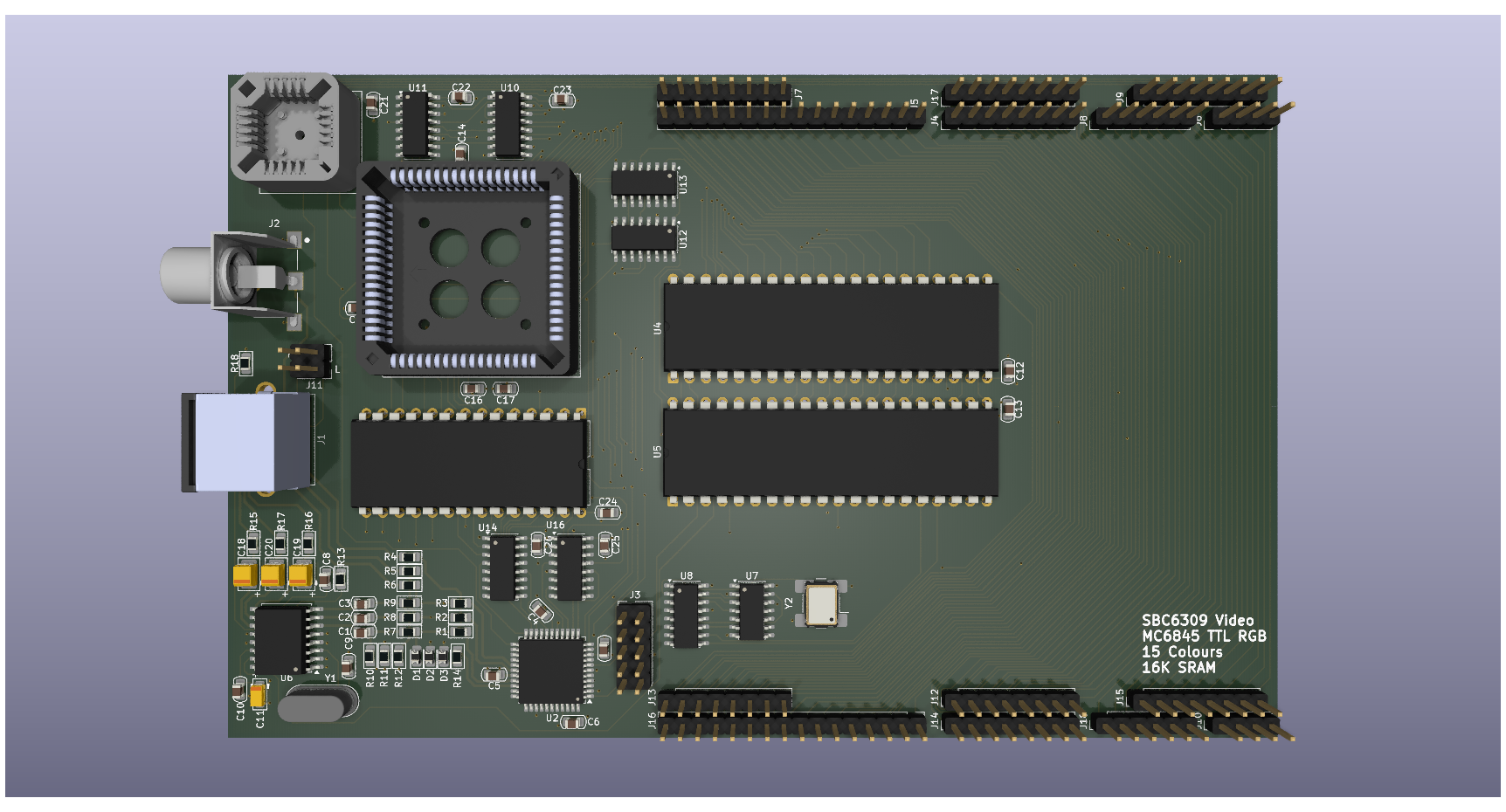
The design is based around a MC6845 CRTC for video timing and sync generation. This is supplemented with a MC6821 to provide additional control over variables outside of the CRTC capability (such as colour palette control)
The conversion of byte data into graphic output is handled by a small CPLD generating TTL RGB (with a half-bright to facilitate 15 colours).
Optionally the RGB is converted to Chroma and Luma for S-video and Composite (all in PAL format). Note the RGB doesn't have to be PAL timing but the composite will not operate correctly if the timing is abused. Conversion is performed by a AD724JRZ encoder.
The pixel clock is generated on the board starting with a 32MHz oscillator, this is divided down to 16, 8, 4 or 2MHz. At the same time the data clock is fixed and synchronised at quarter of the pixel clock.
The choice of divider is controlled by the PIA. Changing the divider requires the CRTC register values to be reset.
To simplify the design the board uses 16K of dual-port SRAM, this decouples the main clock of the computer from the video clock, allowing it to run out of phase without repurcussions. While dual-port ram is expensive, the chip used here can be obtained at a price comparable to regular SRAM (still more expensive but not prohibitively so).
From the perspective of the host the video memory is just an 8K window, the address range is paged via the PIA to expand to the full 16K.
The board uses a 16V8 GAL to integrate the board into the rest of the computer for the purposes of mapping main bus addresses to the video ram and to the CRTC and PIA.
The main video (RGB) output is through a 9-pin mini-din socket, this incorporates stereo audio output not generated on this board. The signal can be injected via a pair of two pin headers.
The objective is to create a single general purpose video board for the SBC6309 project which must include a text-only mode. To achieve this the board needs to incorporate a character generator ROM. A set of 256 characters at 8 bytes per character requires a 2K address space, the CRTC provides row addressing for up to 32 bytes. Assuming the maximum the requirement increases to 8K but a 8 pixel x 32 pixel character is of limited use. A more practical solution is to utilise the 16 byte option and map the rows to 8, 10 or 12. An 8K rom would allow for two different character sets, possibly at different row counts.
Switching between bitmap and character modes can be performed using a simple 74LS157 multiplexer (two required) depending on the mode. Graphic data can be mapped to both the multiplexer directly (bitmap) or via the character rom (text).
The 6845 can address a maximum of 512KB - way beyond the addressing capability of the host. With an 8K window that 64 pages. Expanding to a 16K window would make this more digestable. The cost of dual-port ram would become excessive however to take this to the maximum.
Increasing to 32K (or 64K) falls within reasonable design and cost limits.
The mechanism for expanding the address space is the same as used for text mode, leveraging the row address registers. By adjusting the design for one, the other becomes inherent.
Referring back to the BBC Model A/B and Amstrad CPC the same trick is used. In the BBC the row address is effectively the lower 3 bits of the address so that the bitmap proceeds vertically for 8 bytes before moving to the next horizontal position. The Amstrad moves the row address on so that each row of video data is consecutive but vertically jumps 8 rows before returning to the top (offset by a row) and proceeding again
| Qty | Value | Footprint | References |
|---|---|---|---|
| 21 | 100nF | PCM_Capacitor_SMD_AKL:C_0805_2012Metric_Pad1.15x1.40mm | C1, C2, C3, C10, C12, C13, C14, C15, C16, C17, C21, C22, C23, C24, C25, C26 +5 |
| 8 | Conn_01x08 | Connector_PinHeader_2.54mm:PinHeader_1x08_P2.54mm_Vertical | J4, J7, J9, J12, J13, J14, J15, J17 |
| 6 | 150R | PCM_Resistor_SMD_AKL:R_0805_2012Metric_Pad1.15x1.40mm | R4, R5, R6, R7, R8, R9 |
| 6 | 74LS157 | Package_SO:SOIC-16_3.9x9.9mm_P1.27mm | U10, U11, U12, U13, U14, U16 |
| 6 | 75R | PCM_Resistor_SMD_AKL:R_0805_2012Metric_Pad1.15x1.40mm | R10, R11, R12, R15, R16, R17 |
| 5 | 68R | PCM_Resistor_SMD_AKL:R_0805_2012Metric_Pad1.15x1.40mm | R1, R2, R3, R14, R18 |
| 3 | 1N4148 | Diode_SMD:D_0805_2012Metric_Pad1.15x1.40mm_HandSolder | D1, D2, D3 |
| 3 | 220uF | PCM_Capacitor_Tantalum_SMD_Handsoldering_AKL:CP_EIA-3528-21_Kemet-B | C18, C19, C20 |
| 2 | Conn_01x04 | Connector_PinHeader_2.54mm:PinHeader_1x04_P2.54mm_Vertical | J6, J10 |
| 2 | Conn_01x06 | Connector_PinHeader_2.54mm:PinHeader_1x06_P2.54mm_Vertical | J8, J18 |
| 2 | Conn_01x16 | Connector_PinHeader_2.54mm:PinHeader_1x16_P2.54mm_Vertical | J5, J16 |
| 1 | 10pF | PCM_Capacitor_SMD_AKL:C_0805_2012Metric_Pad1.15x1.40mm | C9 |
| 1 | 10uF | PCM_Capacitor_Tantalum_SMD_Handsoldering_AKL:CP_EIA-3216-10_Kemet-I | C11 |
| 1 | 27C64 | Package_DIP:DIP-28_W15.24mm | U15 |
| 1 | 2K7 | PCM_Resistor_SMD_AKL:R_0805_2012Metric_Pad1.15x1.40mm | R13 |
| 1 | 32MHz | Oscillator:Oscillator_SMD_Abracon_ASV-4Pin_7.0x5.1mm_HandSoldering | Y2 |
| 1 | 4.433618MHz | Crystal:Crystal_HC49-4H_Vertical | Y1 |
| 1 | 74HCT393 | Package_SO:SOIC-14_3.9x8.7mm_P1.27mm | U7 |
| 1 | AD725 | Package_SO:SOIC-16W_7.5x10.3mm_P1.27mm | U6 |
| 1 | ATF1504AS | Package_QFP:TQFP-44_10x10mm_P0.8mm | U2 |
| 1 | Audio | Connector_PinHeader_2.54mm:PinHeader_2x02_P2.54mm_Vertical | J11 |
| 1 | CD4052B | Package_SO:SOIC-16_3.9x9.9mm_P1.27mm | U8 |
| 1 | Conn_Coaxial | Library:CUI_RCJ-013-SMT | J2 |
| 1 | DIN-9 | Library:KMDGX-9S-AS | J1 |
| 1 | GAL16V8 | Library:PLCC-20_THT-Socket | U9 |
| 1 | IDT7006L35J | Library:PLCC-68_THT-Socket | U1 |
| 1 | JTAG | Connector_PinHeader_2.54mm:PinHeader_2x05_P2.54mm_Vertical | J3 |
| 1 | MC68B21 | Package_DIP:DIP-40_W15.24mm | U5 |
| 1 | MC68B45 | Package_DIP:DIP-40_W15.24mm | U4 |
ChartreuseK/RC2014-Z80-CLK-RES
Simple z80 board with onboard clock generator and reset circuitry for RC2014 bus.


GaryMacMinn/65C02-Retro-Computer
A retro computer system based on the 65C02 CPU in a modular form.


qbancoffee/cocoplusplus
So now it's time to have fun.... I want to base this board on the CoCo 3 for several reasons.
It measures 161.3 × 101.9 mm and has 4 copper layers, 1.6 mm thick.
82 parts, built around the 74LS157PC, 74HCT393D and CD4052BM. The full list of its parts is on this page, with links to each part's symbol and footprint where PCBKit's library has them.
From the jimbro1000/SBC6809System2Video repository on GitHub, at the commit this page was made from: the board is SBC6809System2Video.kicad_pcb and its schematic SBC6809System2Video.kicad_sch. PCBKit opens the board in the browser, with nothing to install.
Its repository states no licence, so its author keeps all rights: ask jimbro1000 before reusing the design.