2 layers304.8 × 165.1 mm
Comix-35
schlae/comix-35
The COMIX-35 is an improved clone of the COMX-35 1802 home computer
173 parts138

 jgw4/doppel-1
Great care has been taken to create a custom library of footprints that match the original apple-1. In fact, every symbol on the board is custom.
Doppel-1 is an open-source printed circuit board by jgw4, from the jgw4/doppel-1 repository on GitHub. It is a 2-layer board of 393.7 × 228.6 mm with 173 parts on 287 nets, routed with 22,590 tracks and 299 vias.
It is built around the DM8097N and 74S257DC. Its parts include 45 capacitors, 35 resistors, 11 connectors, 9 diodes and 5 transistors. It belongs with the NXP (LPC, Kinetis, i.MX RT) boards of this library.

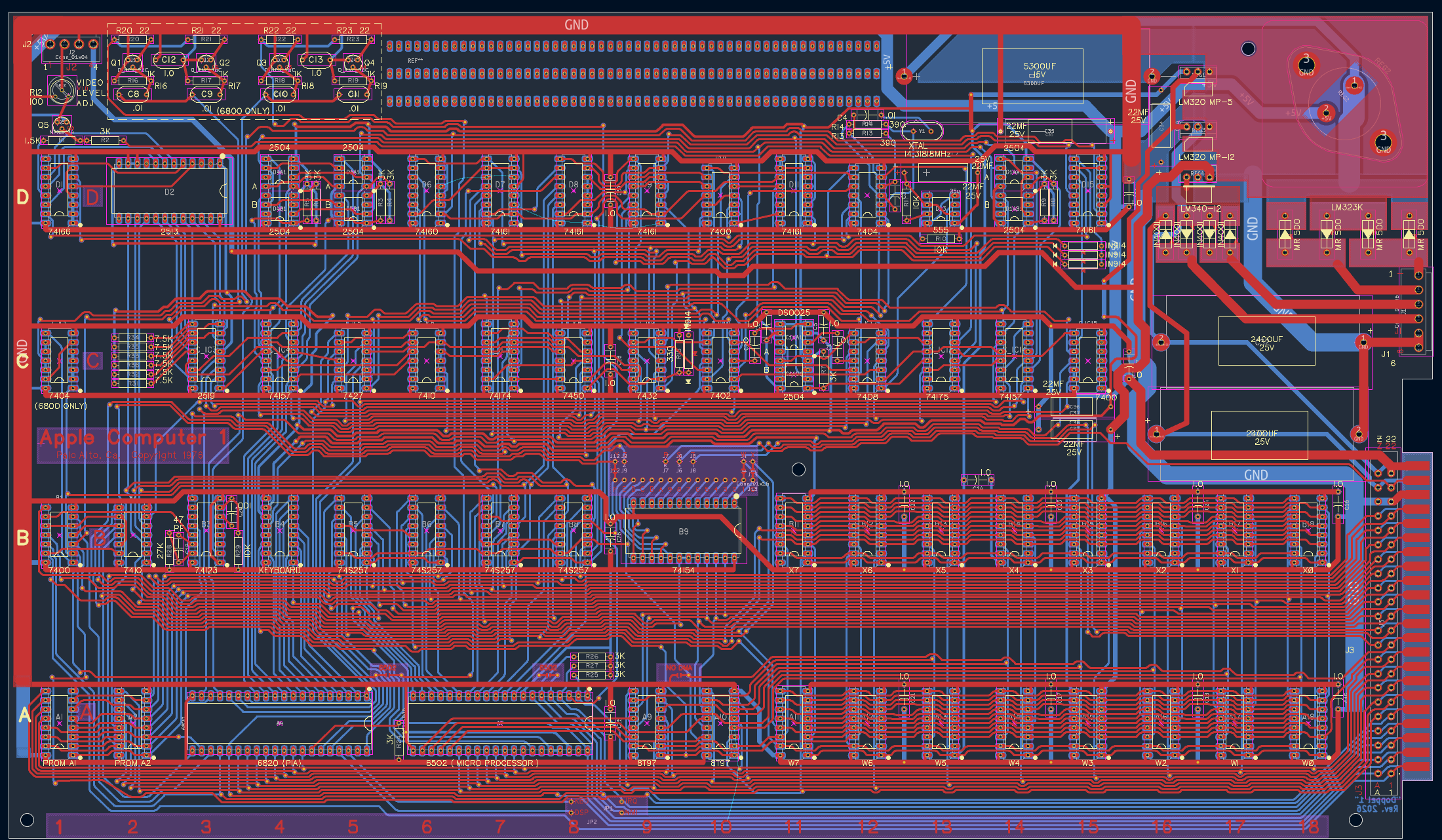 Doppel-1 As of 2026/09/18
This repository contains the "Doppel-1", an Apple-1 Replica PCB. It is unique among clone boards in that the source design files are completely open-source, and It is built in standard EDA fashion, where each component on the board is linked to a symbol on a full schematic of the apple-1. This also allows for generating gerber files at the source, easy modification, and the ability to highlight trace sets on the board via the net selector. This makes it very useful when diagnosing build issues. It also features a near full set of 3d components, which allows an accurate step file to be exported.
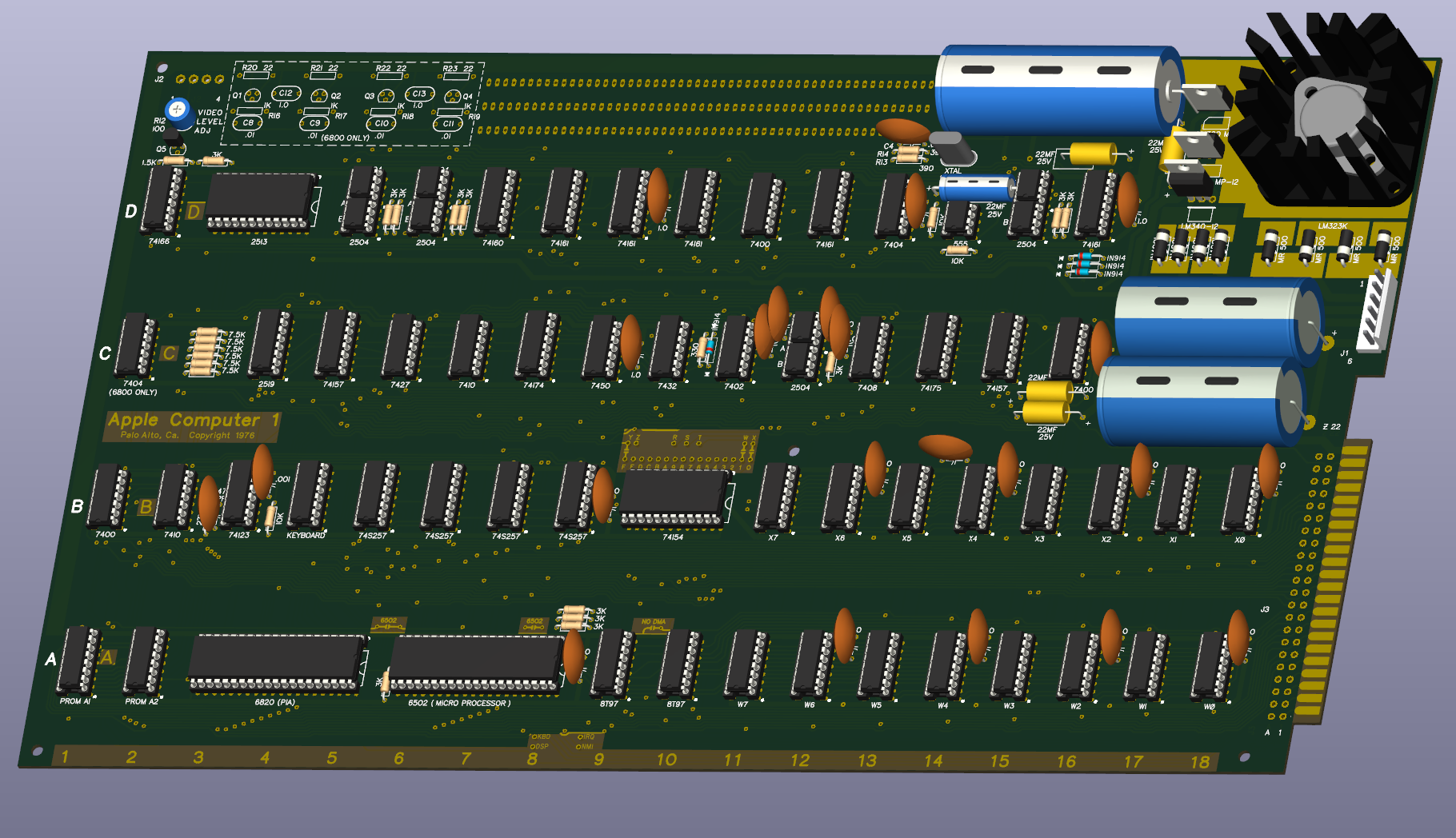 Doppel-1 within KiCad 3D Viewer
Great care has been taken to create a custom library of footprints that match the original apple-1. In fact, every symbol on the board is custom. This preserves the aesthetics of the pads and silkscreens while allowing for pin-pin linkage from the schematic.
Clarifying remarks have been made to ensure that the PCB is being fabricated to make a reasonable replica. If you desire to make your own board from these files, please read the Manufacturing Notes below.
This project started by importing the gerber files for the "PCB-11" replica that I found on Applefritter Forums, which were posted originally on a facebook group. It is the only clone board that I know of where the gerber files have been made publicly available. Little by little, I began replacing gerber features with native KiCad features, until there was almost nothing left of the original gerber (see "Open Issues..." Below). A theseus ship of sorts, but improved.
I have made some remarks about my observations so far:
The silkscreen text on the Apple-1 PCB is extremely difficult to reproduce. By all accounts it was hand-stenciled, and I have spent more time than I care to admit comparing uniform-stroke technical typefaces that are meant to replicate leroy lettering or other technical stencil packages that are freely available online, but none of them have quite matched what I have seen on the PCB-11 and on other clones. I have messed around with the font "Routed Gothic" and found it to be closest but kerning is not quite there, and it still does not match with the characters aforementioned. I can hack my way to passable kerning by adjusting the height-width ratio of the text boxes but it is not ideal. I believe Iwater GMaru Gothic Pro is a better match to the original, however that is a paid font that I am unwilling to obtain due to licensing. For any future work on a custom font for this computer, I have included a character "Proof Area" in the PCB file which contains every character on the board.
The solder pads on the DIP sockets and breadboard area on "PCB-11" are round on both front and back layers, while on original units, the solderpads were actually different on the back side vs the front. On the back they were a squashed oval (basically an obround but the end arcs share a center point with the rectangle's center point), and on the front they were smaller, tangent obrounds. This was most likely done to make it easy to solder while leaving room for trace paths on the front. This is something a lot of replicas miss.
The trace leading to the positive lead between B&C @16 has been adjusted to match the Mimeo-1
The trace between C&D @15 leeting to the via below IN914 diode at a 45 degree angle has been moved down slightly to match the Mimeo-1
silkscreen outlines for DIP sockets has been increased to a width of 10mils to match what is expected
In the original manual's schematics, as well as the ones made by Nicolas, there is an error in the pinouts listed for the TO-220 diodes (REG1,REG3,REG4/LM320 MP-5/LM320 MP-12/LM340 MP-12). LM320 has ground at pin 1, while in and out are pins 2&3, respectively.LM340 has ground at 2 and in/out at 1/3 like a more standard diode in this package. This was discovered by DRC error checking.
The top right mounting via has been moved right 100mils to match Mike Willegal's case dimension here. My assumption is that these are truer than what were originally on the board
The original applefritter post had a user comment that noted the following issues. My comments are appended to the original marks:
If you are going to get your own replica board manufactured, read this first:
Boards are to be purchased at your own risk. I do not take responsibility for any defects, design or otherwise, contained within your finished boards.
Normally the green finish provided by PCB manufacturers is way too dark. It has become clear to me that it will be almost impossible to replicate near-exact finishes for small volume with any direct-to-customer fabricators. If the fabricator does allow for lighter green finishes and/or matte green, these colors should be selected instead of a "Standard" green.
Boards that are finished with an ENIG process (i.e. full-board gold plating) are unable to also accomodate silkscreening on top of non-soldermasked copper. This is extremely evident in the top-right corner of the board where diode markings are missing where the gold is plated over the copper. It is understandable to desire gold for the longevity of the board, but doing so will produce a poor replica. ENIG is also not sufficient for edge fingers; since ENIG is a softer finish, it will wear just as if it were plated like a standard PCB. Hard Gold plating (not ENIG) is best for edge fingers, and should be confined to the edge fingers only, with the rest done in HAL SnPb.
I request that anyone exporting their own gerbers to not remove the replica signifying text on the bottom right on the back of the board. This board contains "Doppel-1 Rev. 2026" on the back copper layer underneath a silkscreen, so it is very discrete. While I think that there are many people out there that can detect replica boards without an unambiguous stamp on the board, I request all reading to preserve the marking to avoid the perception or attempts at counterfeiting.
I have had a strange fascination for the Apple-1 ever since I was a kid. Even though I am not a competent electronics hobbyist or electrical engineer, I've been drawn to the technical artistry of the board, and find the assembly process and case design around it a very cool method of self-expression. I suppose also there is a love of historical artifact that comes with people who love these computers too, and I am very much in that camp.
To properly view some of the pcb file's text elements, you may need to download and install "Routed Gothic" font located in /doc/. This is the closest match I have found to the original PCB lettering in font form and is based on the Leroy stenciling system common with draftsman before computer fonts.
I have a near certain guess that the original apple-1 pcb was designed using mils. Thus, I would strongly encourage any user working on this board to set their units to mils and not mm. The original PCB-11 file was most likely not made by an American, as there are many metric dimensions scattered throughout the document. However building in nice round mil numbers should be the standard for this project
please submit a pull request listing in detail all changes you have made or would like to make, preferably with pictures. This can help avoid any duplicate work. I can infer many changes by inspecting the changed files as text, but a more human-readable explanation helps.
Issues can also be raised, which I also enthusiastically accept. If you spot issues with the design of the board, please post an issue to the repository.
I am looking also for some more specific input on trace clearance. Since resizing the dip solderpads, clearance has been the biggest DRC issue. I would like to know what spacing was used on the original board so I can preserve that. Current clearance is set at 5 mils.
Erik's Ponderings - Building an Apple-1 - Erik Bruchez documented his process of building an exceptional Apple-1 clone in great detail, including some great tips for power supply building, adding more decoupling capacitors, mechanical tips, and more. Really neat to check out, especially before you build one of your own
| Qty | Value | Footprint | References |
|---|---|---|---|
| 16 | MK4096 | mainboard:apple-1_DIP-16_W7.62mm | A11, A12, A13, A14, A15, A16, A17, A18, B11, B12, B13, B14, B15, B16, B17, B18 |
| 12 | 3K | mainboard:apple-1_R_Axial_DIN0207_L6.3mm_D2.5mm_P10.16mm_Horizontal | R2, R3, R4, R5, R6, R7, R8, R9, R24, R25, R26, R27 |
| 8 | 1.0u | mainboard:apple-1_C_Disc_D16.0mm_W5.0mm_P275mils | C15, C16, C17, C18, C21, C22, C23, C24 |
| 7 | 1.0u | mainboard:apple-1_C_Disc_D16.0mm_W5.0mm_P7.50mm | C14, C25, C26, C27, C28, C29, C30 |
| 7 | 2504 | mainboard:apple-1_DIP-8_W7.62mm | C11B1, D4A1, D4B1, D5A1, D5B1, D14A1, D14B1 |
| 6 | 7.5K | mainboard:apple-1_R_Axial_DIN0207_L6.3mm_D2.5mm_P10.16mm_Horizontal | R31, R32, R33, R34, R35, R36 |
| 5 | 74161 | mainboard:apple-1_DIP-16_W7.62mm | D7, D8, D9, D11, D15 |
| 4 | .01 | mainboard:apple-1_C_Disc_D16.0mm_W5.0mm_P7.50mm | C1, C2, C3, C4 |
| 4 | .01 | mainboard:apple-1_C_Disc_D16.0mm_W5.0mm_P7.50mm (68000 section) | C8, C9, C10, C11 |
| 4 | 1K | mainboard:apple-1_R_Axial_DIN0207_L6.3mm_D2.5mm_P10.16mm_Horizontal | R16, R17, R18, R19 |
| 4 | 1N4001 | mainboard:apple-1_D_5W_P10.16mm_Horizontal | DI5, DI6, DI7, DI8 |
| 4 | 1N914 | mainboard:apple-1_D_DO-35_SOD27_P10.16mm_Horizontal_altarrow | CR1, CR2, CR3, CR4 |
| 4 | 22 | mainboard:apple-1_R_Axial_DIN0207_L6.3mm_D2.5mm_P10.16mm_Horizontal | R20, R21, R22, R23 |
| 4 | 74S257 | mainboard:apple-1_DIP-16_W7.62mm | B5, B6, B7, B8 |
| 4 | MR 500 | mainboard:apple-1_D_5W_P10.16mm_Horizontal | DI1, DI2, DI3, DI4 |
| 3 | 10K | mainboard:apple-1_R_Axial_DIN0207_L6.3mm_D2.5mm_P10.16mm_Horizontal | R10, R11, R29 |
| 3 | 22MF | mainboard:apple-1_C_Axial_L12.0mm_D6.5mm_P20.00mm_Horizontal | C34, C36, C37 |
| 3 | 7400 | mainboard:apple-1_DIP-14_W7.62mm | B1, C_IC15, D10 |
| 2 | 1.0 | mainboard:apple-1_C_Disc_D16.0mm_W5.0mm_P7.50mm | C5, C6 |
| 2 | 1.0 | mainboard:apple-1_C_Disc_D16.0mm_W5.0mm_P7.50mm (68000 section) | C12, C13 |
| 2 | 2400UF | mainboard:apple-1_CP_2400UF_25V_-+ | C32, C33 |
| 2 | 390 | mainboard:apple-1_R_Axial_DIN0207_L6.3mm_D2.5mm_P10.16mm_Horizontal | R13, R14 |
| 2 | 7404 | mainboard:apple-1_DIP-14_W7.62mm | C_IC1, D12 |
| 2 | 7410 | mainboard:apple-1_DIP-14_W7.62mm | B2, C_IC6 |
| 2 | 74157 | mainboard:apple-1_DIP-16_W7.62mm | C_IC4, C_IC14 |
| 2 | DM8097 | mainboard:apple-1_DIP-16_W7.62mm | A9, A10 |
| 2 | MMI6301 | mainboard:apple-1_DIP-16_W7.62mm | A1, A2 |
| 2 | Q_NPN_EBC | mainboard:apple-1_TO-92_HandSolder | Q1, Q3 |
| 2 | Q_PNP_EBC | mainboard:apple-1_TO-92_HandSolder | Q2, Q4 |
| 1 | .001 | mainboard:apple-1_C_Disc_D16.0mm_W5.0mm_P7.50mm | C20 |
| 1 | 1.5K | mainboard:apple-1_R_Axial_DIN0207_L6.3mm_D2.5mm_P10.16mm_Horizontal | R1 |
| 1 | 100 | mainboard:apple-1_Potentiometer_Bourns_3329H_Vertical | R12 |
| 1 | 14.31818 MHz | mainboard:apple-1_Crystal_HC49-U_Vertical | Y1 |
| 1 | 22MF | mainboard:apple-1_C_Axial_22MF_25V_P1200mils_Horizontal | C35 |
| 1 | 2513 | mainboard:apple-1_DIP-24_18.0mmx34.29mm_W15.24mm | D2 |
| 1 | 2519 | mainboard:apple-1_DIP-16_W7.62mm | C_IC3 |
| 1 | 25u | mainboard:CP_Axial_25u | C7 |
| 1 | 27K | mainboard:apple-1_R_Axial_DIN0207_L6.3mm_D2.5mm_P10.16mm_Horizontal | R28 |
| 1 | 330 | mainboard:apple-1_R_Axial_DIN0207_L6.3mm_D2.5mm_P10.16mm_Horizontal | R15 |
| 1 | 47 PF | mainboard:apple-1_C_Disc_D16.0mm_W5.0mm_P7.50mm | C19 |
| 1 | 5300UF | mainboard:CP_Axial_5300uF | C31 |
| 1 | 555 | mainboard:apple-1_DIP-8_W7.62mm | D13 |
| 1 | 6502_6800 | mainboard:apple-1_DIP-40_W15.24mm | A7 |
| 1 | 6820 | mainboard:apple-1_DIP-40_W15.24mm | A4 |
| 1 | 7402 | mainboard:apple-1_DIP-14_W7.62mm | C_IC10 |
| 1 | 7408 | mainboard:apple-1_DIP-14_W7.62mm | C_IC12 |
| 1 | 74123 | mainboard:apple-1_DIP-16_W7.62mm | B3 |
| 1 | 74154 | mainboard:apple-1_DIP-24_18.0mmx34.29mm_W15.24mm | B9 |
| 1 | 74160 | mainboard:apple-1_DIP-16_W7.62mm | D6 |
| 1 | 74166 | mainboard:apple-1_DIP-16_W7.62mm | D1 |
| 1 | 74174 | mainboard:apple-1_DIP-16_W7.62mm | C_IC7 |
| 1 | 74175 | mainboard:apple-1_DIP-16_W7.62mm | C_IC13 |
| 1 | 7427 | mainboard:apple-1_DIP-14_W7.62mm | C_IC5 |
| 1 | 7432 | mainboard:apple-1_DIP-14_W7.62mm | C_IC9 |
| 1 | 7450 | mainboard:apple-1_DIP-14_W7.62mm | C_IC8 |
| 1 | Conn_01x04 | mainboard:apple-1_JST_VH_B4P-VH_1x04_P3.96mm_Vertical | J2 |
| 1 | Conn_01x06 | mainboard:apple-1_JST_VH_B6P-VH_1x06_P3.96mm_Vertical | J1 |
| 1 | Conn_01x16 | mainboard:J13 | J13 |
| 1 | DS0025 | mainboard:apple-1_DIP-8_W7.62mm | C11A1 |
| 1 | EDAC 305-044-520-201 | mainboard:307044520201 | J3 |
| 1 | Jumper_NO_Small | mainboard:apple-1_DSP-NMI | JP2 |
| 1 | Jumper_NO_Small | mainboard:apple-1_KBD-IRQ | JP1 |
| 1 | KEYBOARD | mainboard:apple-1_DIP-16_W7.62mm | B4 |
| 1 | LM320 MP-12 | mainboard:LM320 MP-12 (TO-220-3_Vertical_SpacedPins) | REG3 |
| 1 | LM320 MP-5 | mainboard:LM320 MP-5 (TO-220-3_Vertical_SpacedPins) | REG1 |
| 1 | LM323 | mainboard:TO-3 | REG2 |
| 1 | LM340 MP-12 | mainboard:LM340-12 (TO-220-3_Vertical_SpacedPins) | REG4 |
| 1 | MPS3704 | mainboard:apple-1_TO-92_HandSolder | Q5 |
| 1 | R | mainboard:RJumper | J7 |
| 1 | S | mainboard:SJumper | J6 |
| 1 | T | mainboard:TJumper | J8 |
| 1 | W | mainboard:WJumper | J4 |
| 1 | X | mainboard:XJumper | J5 |
| 1 | Y | mainboard:YJumper | J12 |
| 1 | Z | mainboard:ZJumper | J9 |
The 170 most common of 173 parts.
It measures 393.7 × 228.6 mm and has 2 copper layers, 1.6 mm thick.
173 parts, built around the DM8097N and 74S257DC. The full list of its parts is on this page, with links to each part's symbol and footprint where PCBKit's library has them.
From the jgw4/doppel-1 repository on GitHub, at the commit this page was made from: the board is d1.kicad_pcb and its schematic d1.kicad_sch. PCBKit opens the board in the browser, with nothing to install.
Its repository states no licence, so its author keeps all rights: ask jgw4 before reusing the design.
schlae/comix-35
The COMIX-35 is an improved clone of the COMX-35 1802 home computer

nicolacimmino/PLC-14500
Retro trainer board based on the MC14500 1-bit ICU. The project is OSHW certified and a ready to assemble kit is available on Tindie.

yiancar/gingham_usbc_pcb
A 60% throughole keyboard with USBC. Inspired by the Plaid

schlae/HardDriveInfo
Repair info and schematics for mostly older MFM hard drives

96boards/mezzanine-community
Repository for community designed mezzanine boards for the 96boards specification.


DragonMinded/minidragon
Hardware and software files for the MiniDragon CPU.