4 layers99 × 99 mm
PrntrBoardV1
ghent360/PrntrBoard
3D Printer controller board using STM32 NUCLEO-F446 kit TMC2130/2660/2209 drivers
238 parts24

 jerinabr/Drone_ESC_Bridge
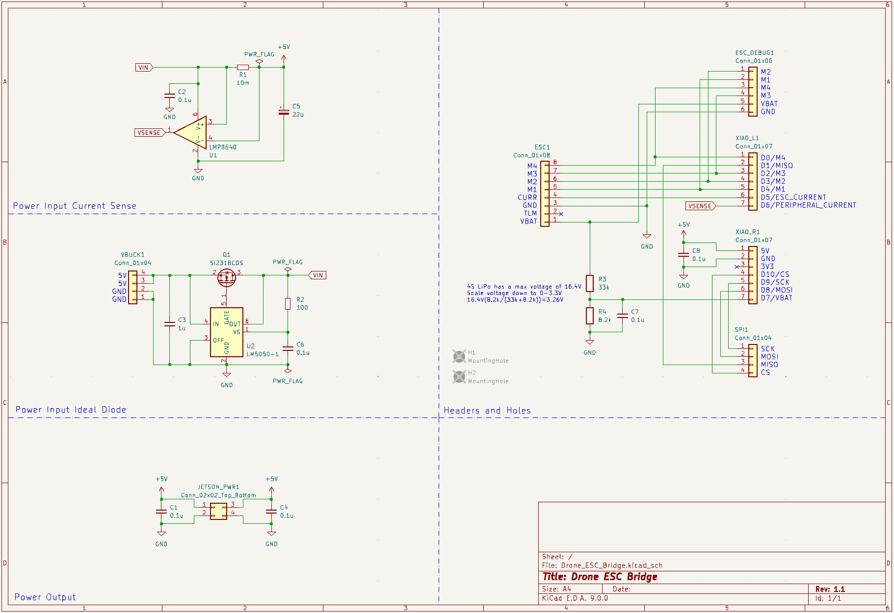
PCB that allows the NVIDIA Jetson to communicate with the 4-in-1 ESC for the drone
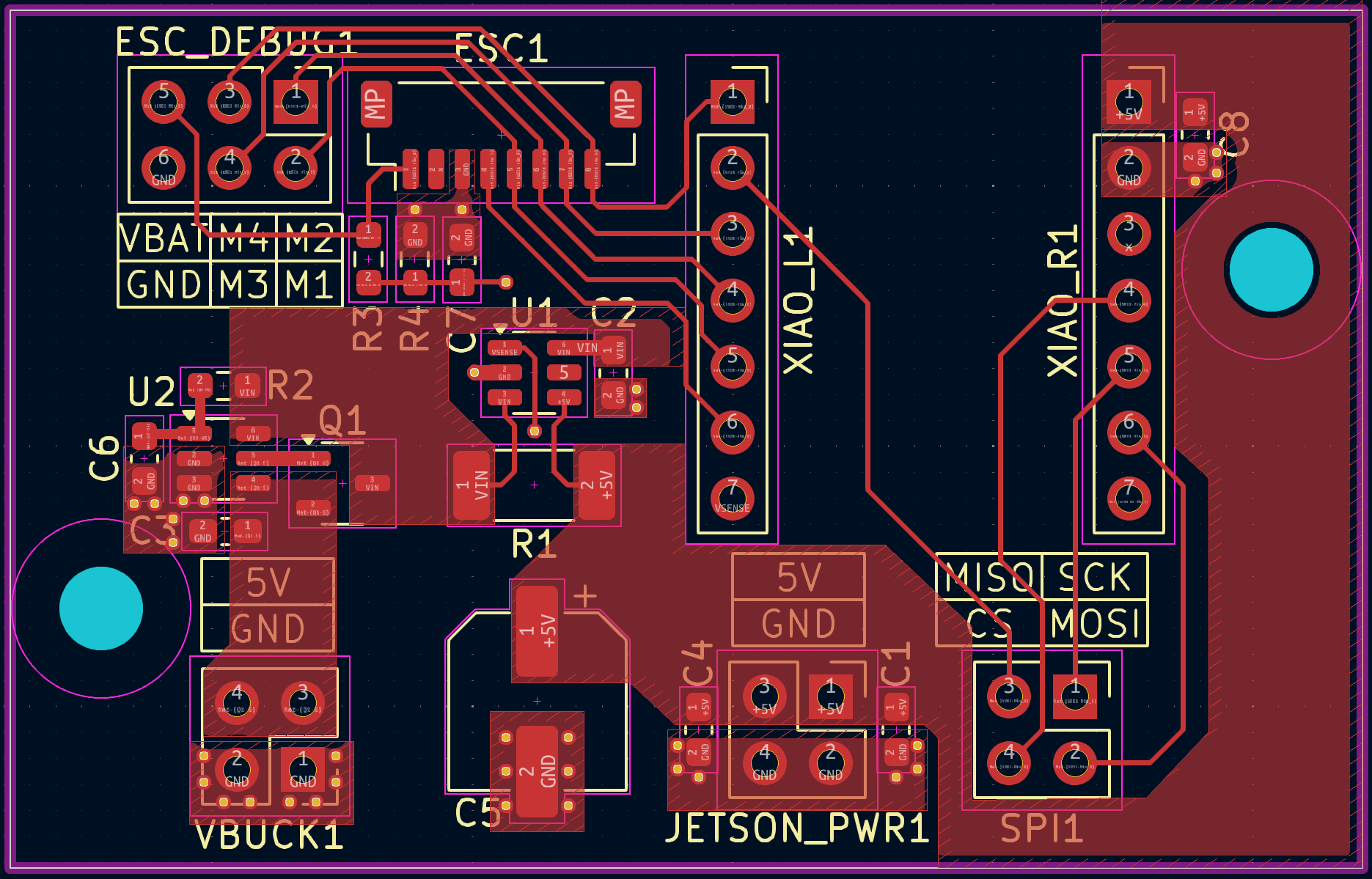
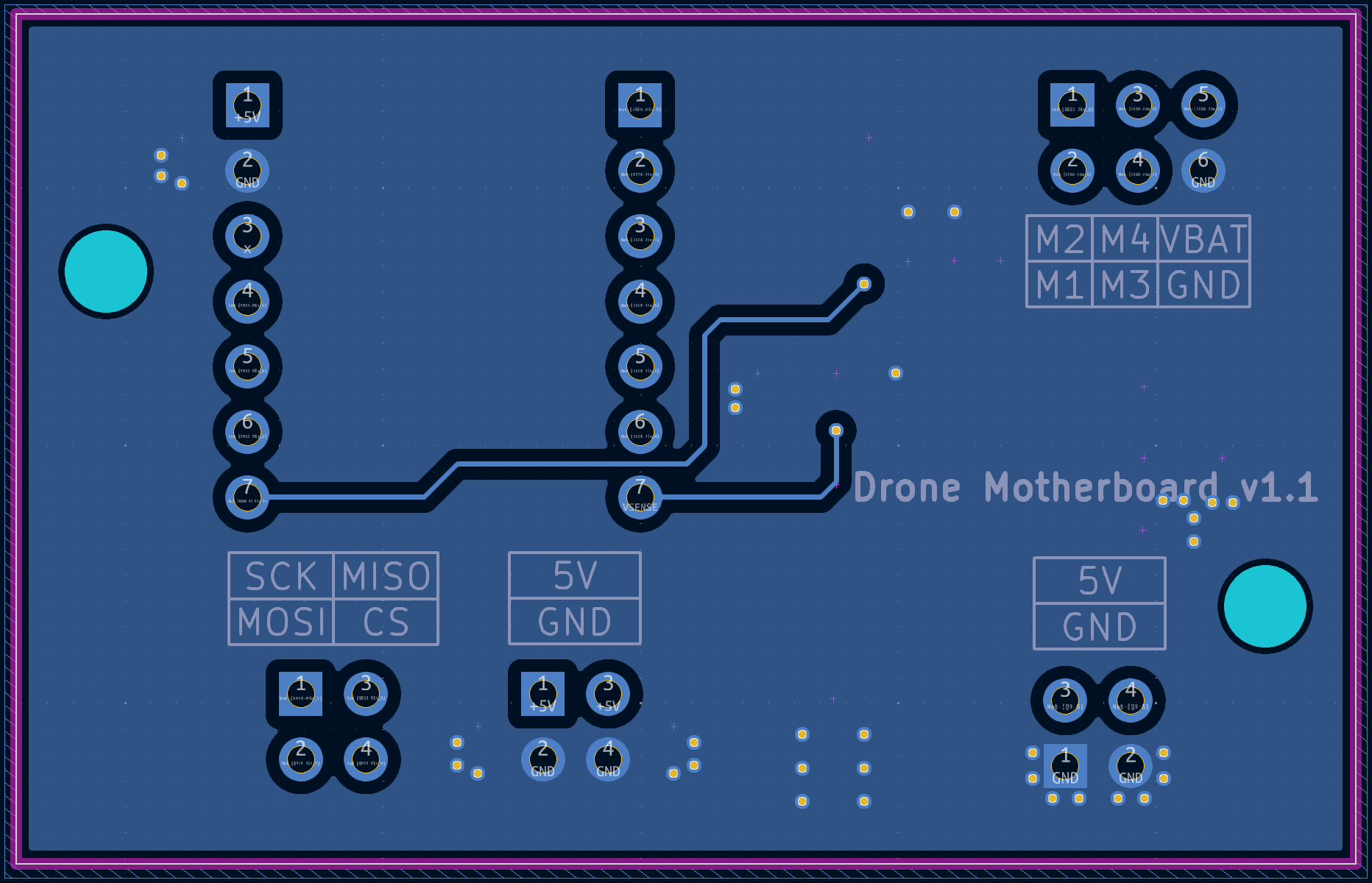
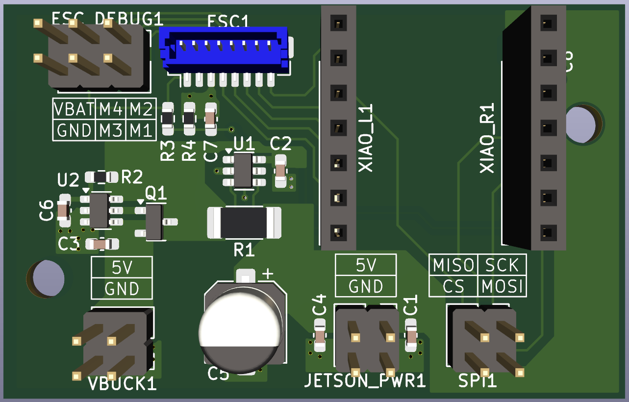
Drone ESC Bridge is an open-source printed circuit board by jerinabr, from the jerinabr/Drone_ESC_Bridge repository on GitHub. It is a 2-layer board of 52 × 33 mm with 24 parts on 20 nets, routed with 108 tracks and 36 vias.
It is built around the LMP8640MK-F and SI2318CDS. Its parts include 8 capacitors, 4 resistors, 2 ICs and 1 transistor. It belongs with the robots and motor control and interfaces and adapters boards of this library.


This board is intended to act as a bridge between the Nvidia Jetson and the 4-in-1 ESC on the ADP drone1
It recieves motor speeds and other commands from the Jetson over the SPI interface and outputs motor speeds to the ESC over PWM
It also monitors the LiPo voltage and can report it back to the Jetson over the SPI interface
The board receives 5V power from an off-board buck converter which is used to power both the microcontroller (Seeed XIAO SAMD21) and the Jetson
| Reference | Value | Footprint | Qty | DigiKey Part Number |
|---|---|---|---|---|
| C1,C2,C4,C6,C7,C8 | 0.1u | Capacitor_SMD:C_0603_1608Metric_Pad1.08x0.95mm_HandSolder | 6 | 311-1088-1-ND |
| C3 | 1u | Capacitor_SMD:C_0603_1608Metric_Pad1.08x0.95mm_HandSolder | 1 | 311-1446-1-ND |
| C5 | 22u | Capacitor_SMD:CP_Elec_6.3x5.8 | 1 | PCE3811CT-ND |
| ESC1 | Conn_01x08 | Connector_JST:JST_SH_BM08B-SRSS-TB_1x08-1MP_P1.00mm_Vertical | 1 | 455-BM08B-SRSS-TBCT-ND |
| ESC_DEBUG1 | Conn_01x06 | Connector_PinHeader_2.54mm:PinHeader_2x03_P2.54mm_Vertical | 1 | 2057-PH2-06-UA-ND |
| JETSON_PWR1 | Conn_02x02_Top_Bottom | Connector_PinHeader_2.54mm:PinHeader_2x02_P2.54mm_Vertical | 1 | 2057-PH2-04-UA-ND |
| Q1 | Si2318CDS | Package_TO_SOT_SMD:SOT-23-3 | 1 | SI2318CDS-T1-GE3CT-ND |
| R1 | 10m | Resistor_SMD:R_2010_5025Metric_Pad1.40x2.65mm_HandSolder | 1 | 13-PE2010FKE070R01LCT-ND |
| R2 | 100 | Resistor_SMD:R_0603_1608Metric_Pad0.98x0.95mm_HandSolder | 1 | 311-100HRCT-ND |
| R3 | 33k | Resistor_SMD:R_0603_1608Metric_Pad0.98x0.95mm_HandSolder | 1 | 311-33.0KHRTR-ND |
| R4 | 8.2k | Resistor_SMD:R_0603_1608Metric_Pad0.98x0.95mm_HandSolder | 1 | 311-8.2KGRTR-ND |
| SPI1,VBUCK1 | Conn_01x04 | Connector_PinHeader_2.54mm:PinHeader_2x02_P2.54mm_Vertical | 2 | 2057-PH2-04-UA-ND |
| U1 | LMP8640 | Package_TO_SOT_SMD:SOT-23-6 | 1 | 296-48927-1-ND |
| U2 | LM5050-1 | Package_TO_SOT_SMD:TSOT-23-6 | 1 | 296-46427-1-ND |
| XIAO_L1,XIAO_R1 | Conn_01x07 | Connector_PinSocket_2.54mm:PinSocket_1x07_P2.54mm_Vertical | 2 | S7040-ND |
[!NOTE]
JETSON_PWR1has the same part number hasSPI1andVBUCK1
They're separate entries because the connector footprint used in the schematic was different
| Qty | Value | Footprint | References |
|---|---|---|---|
| 6 | 0.1u | Capacitor_SMD:C_0603_1608Metric_Pad1.08x0.95mm_HandSolder | C1, C2, C4, C6, C7, C8 |
| 2 | Conn_01x04 | Connector_PinHeader_2.54mm:PinHeader_2x02_P2.54mm_Vertical | SPI1, VBUCK1 |
| 2 | Conn_01x07 | Connector_PinSocket_2.54mm:PinSocket_1x07_P2.54mm_Vertical | XIAO_L1, XIAO_R1 |
| 2 | MountingHole | MountingHole:MountingHole_3.2mm_M3 | H1, H2 |
| 1 | 100 | Resistor_SMD:R_0603_1608Metric_Pad0.98x0.95mm_HandSolder | R2 |
| 1 | 10m | Resistor_SMD:R_2010_5025Metric_Pad1.40x2.65mm_HandSolder | R1 |
| 1 | 1u | Capacitor_SMD:C_0603_1608Metric_Pad1.08x0.95mm_HandSolder | C3 |
| 1 | 22u | Capacitor_SMD:CP_Elec_6.3x5.8 | C5 |
| 1 | 33k | Resistor_SMD:R_0603_1608Metric_Pad0.98x0.95mm_HandSolder | R3 |
| 1 | 8.2k | Resistor_SMD:R_0603_1608Metric_Pad0.98x0.95mm_HandSolder | R4 |
| 1 | Conn_01x06 | Connector_PinHeader_2.54mm:PinHeader_2x03_P2.54mm_Vertical | ESC_DEBUG1 |
| 1 | Conn_01x08 | Connector_JST:JST_SH_BM08B-SRSS-TB_1x08-1MP_P1.00mm_Vertical | ESC1 |
| 1 | Conn_02x02_Top_Bottom | Connector_PinHeader_2.54mm:PinHeader_2x02_P2.54mm_Vertical | JETSON_PWR1 |
| 1 | LM5050-1 | Package_TO_SOT_SMD:TSOT-23-6 | U2 |
| 1 | LMP8640 | Package_TO_SOT_SMD:SOT-23-6 | U1 |
| 1 | Si2318CDS | Package_TO_SOT_SMD:SOT-23-3 | Q1 |
ghent360/PrntrBoard
3D Printer controller board using STM32 NUCLEO-F446 kit TMC2130/2660/2209 drivers

Fescron/2ch-4-20mA-converter
1/2 channel 4-20 mA to voltage converter boards using LMP8640 current sense monitor.

eflukx/Linear-motor-window-controller
Linear quad/octa motor slide Window controller, featuring absolute position feedback control, motor current monitoring using a ESP32-S3 hi performance controller

Fescron/masterthesis
This repository is a collection of hardware, firmware and some documentation files for the project I created for my masterthesis.


dotnet/iot
This repo includes .NET Core implementations for various IoT boards, chips, displays and PCBs.

pascallanger/DIY-Multiprotocol-TX-Module
Multiprotocol TX Module (or MULTI-Module) is a 2.4GHz transmitter module which controls many different receivers and models.
It measures 52 × 33 mm and has 2 copper layers, 1.6 mm thick.
24 parts, built around the LMP8640MK-F and SI2318CDS. The full list of its parts is on this page, with links to each part's symbol and footprint where PCBKit's library has them.
From the jerinabr/Drone_ESC_Bridge repository on GitHub, at the commit this page was made from: the board is Drone_ESC_Bridge.kicad_pcb and its schematic Drone_ESC_Bridge.kicad_sch. PCBKit opens the board in the browser, with nothing to install.
Its repository states no licence, so its author keeps all rights: ask jerinabr before reusing the design.