
Homeautomation2
kehindejanetolaniyi23/home-automation-kicad-work-in-progress
Work-in-progress KiCad PCB design for a home automation relay and power monitoring board, including schematic review, PCB layout review, and DRC improvement notes.

Convenient current transformer PCB with support for common transformers
EasyCT is an open-source printed circuit board by JeppeKlitgaard, from the JeppeKlitgaard/EasyCT repository on GitHub, published under the MIT licence. It is a 2-layer board of 25.4 × 53.3 mm with 43 parts on 21 nets, routed with 179 tracks and 10 vias.
It is built around the LMV321, RT9193-30GB and 1N5819W, with the ZMCT103C and ZMCT118F among its other parts. Its parts include 11 resistors, 9 capacitors, 7 diodes, 3 ICs and 3 connectors.
EasyCT supports most current-mode current transformers (that is, current transformers without a built-in burden resistor). These will have their outputs listed as currents (typically $\textrm{mA}$ or $\textrm{A}$), not voltages ($\textrm{mV, V}$)
Additionally the PCB footprint has support for the following transformers:
The burden resistance $R_\text{burden}$ sets the resistance used to create the sense voltage $V_\text{sense}$ using the current from the transformer according to the network shown below, which allows for a wide range of currents. The target $V_\text{sense}$ is about $1\text{V}$, which is doubled by an op-amp amplifier and compared against the trigger voltage, $V_\text{trigger}$, set by the $200kΩ$ potentiometer.
The potentiometer can be tuned to the desired trigger voltage by playing around with the circuit.
.
I use one of these with a relay to turn on a dust extractor when a large Robland table saw is on. Because the table saw has multiple tools running on separate circuits, and because I don't like to work with mains voltage, it is not possible to directly hook into the mains going to the saw. Further, the saw is 3 phase and additionally draws a standby current for the magnetic clutch for the on-switch, which complicates other potential solutions.
This circuit is very easy to use with any tool that runs on AC voltage and can be used entirely without making electrical contact with mains power.
Update: after 3 years of operation the circuit started flickering on and off. It had been sitting inside of a table saw, so maybe vibration caused the trim pot to shift, or capacitors started leaking a bit more, or oxide built up in the trim pot causing the $V_\text{trigger}$ to shift. In any case, the fix was simply adjusting the trim pot back into a working position.
| Qty | Value | Footprint | References |
|---|---|---|---|
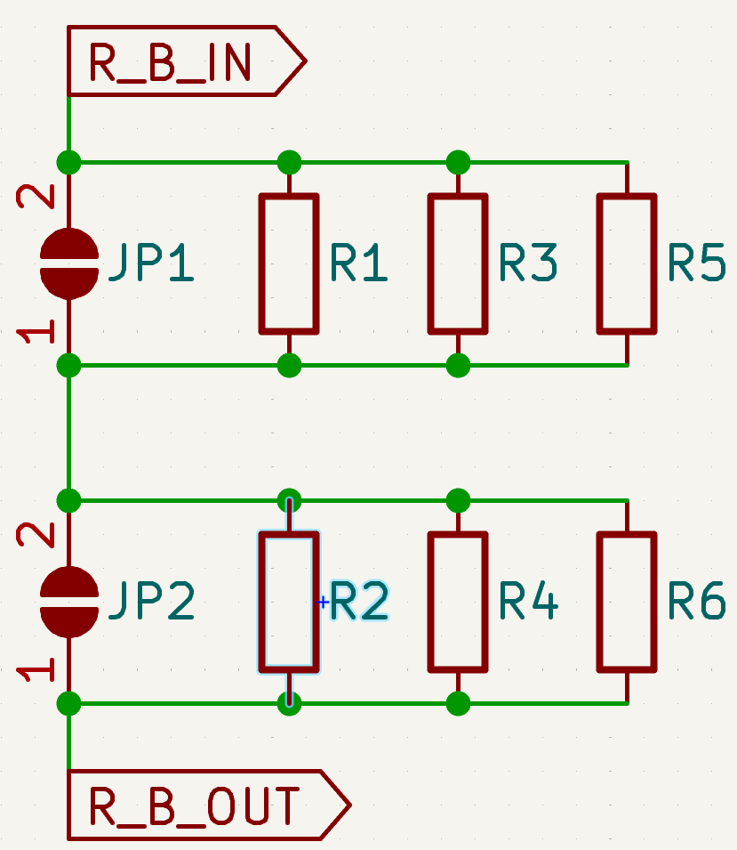
| 6 | R | Resistor_THT:R_Axial_DIN0207_L6.3mm_D2.5mm_P7.62mm_Horizontal | R1, R2, R3, R4, R5, R6 |
| 4 | 100nF | Capacitor_SMD:C_0805_2012Metric | C1, C3, C7, C8 |
| 4 | 1N4148 | Diode_SMD:D_SOD-123 | D1, D2, D3, D4 |
| 3 | 1N5819W | Diode_SMD:D_SOD-323 | D5, D6, D7 |
| 3 | 47K | Resistor_SMD:R_0805_2012Metric | R7, R8, R9 |
| 3 | MountingHole | MountingHole:MountingHole_3.2mm_M3 | H1, H2, H3 |
| 2 | 4.7μF | Capacitor_SMD:C_0805_2012Metric | C2, C5 |
| 2 | LMV321 | Package_TO_SOT_SMD:SOT-23-5 | U2, U3 |
| 2 | SolderJumper_2_Open | Jumper:SolderJumper-2_P1.3mm_Open_TrianglePad1.0x1.5mm | JP1, JP2 |
| 1 | 0.1μF | Capacitor_SMD:C_0805_2012Metric | C6 |
| 1 | 10nF | Capacitor_SMD:C_0805_2012Metric | C4 |
| 1 | 10μF | Capacitor_SMD:C_0805_2012Metric | C9 |
| 1 | 1K | Resistor_SMD:R_0805_2012Metric | R11 |
| 1 | 1M | Resistor_SMD:R_0805_2012Metric | R10 |
| 1 | 200K | Potentiometer_THT:Potentiometer_Bourns_3296W_Vertical | RV1 |
| 1 | IRLML0040TRPbF | Package_TO_SOT_SMD:SOT-23 | Q1 |
| 1 | RT9193-30GB | EasyCT_Vendored:SOT-23-5_L3.0-W1.7-P0.95-LS2.8-BR | U1 |
| 1 | SCT013 | EasyCT_Vendored:AUDIO-TH_HOOYA_PJ-320 | CN1 |
| 1 | Screw_Terminal_01x02 | EasyCT_Vendored:CONN-TH_XY308-2.54-2P | J1 |
| 1 | Screw_Terminal_01x07 | EasyCT_Vendored:CONN-TH_XY308-2.54-7P | J2 |
| 1 | TestPoint_2Pole | TestPoint:TestPoint_2Pads_Pitch5.08mm_Drill1.3mm | TP1 |
| 1 | ZMCT103C | EasyCT:Current_Transformer_CT_ZMCT103C | L1 |
| 1 | ZMCT118F | EasyCT_Vendored:XFMR-TH_ZMCT118F | L2 |
It measures 25.4 × 53.3 mm and has 2 copper layers, 1.6 mm thick.
43 parts, built around the LMV321, RT9193-30GB, 1N5819W and ZMCT103C. The full list of its parts is on this page, with links to each part's symbol and footprint where PCBKit's library has them.
From the JeppeKlitgaard/EasyCT repository on GitHub, at the commit this page was made from: the board is EasyCT.kicad_pcb and its schematic EasyCT.kicad_sch. PCBKit opens the board in the browser, with nothing to install.
Its repository publishes it under the MIT licence: you may reuse it on that licence's terms (keep the author's notice, and for a copyleft licence share your changes alike).

kehindejanetolaniyi23/home-automation-kicad-work-in-progress
Work-in-progress KiCad PCB design for a home automation relay and power monitoring board, including schematic review, PCB layout review, and DRC improvement notes.


wa1hco/rotator_controller
Clean slate rebuild of full featured rotator controller.


hackclub/OnBoard
💡 Join 1,000 teenagers and make your first PCB with a $100 grant!
![[DFR1144][M027.00940](V1.0.0), the printed circuit board in 3D](/embed/boards/lattepandateam-lattepanda-mu-dfr1144-m027-00940-v1-0-0.jpg?size=s&soon)
LattePandaTeam/LattePanda-Mu
All About LattePanda Mu N100/N305 Compute Module