2 layers150 × 26 mm

 jeffkub/nixie-clock2
An open source nixie clock with GPS time synchronization.
Nixie clock is an open-source printed circuit board by jeffkub, from the jeffkub/nixie-clock repository on GitHub, published under the MIT licence. It is a 2-layer board of 176 × 55 mm with 106 parts on 99 nets, routed with 823 tracks and 163 vias.
It is built around the STM32F302CBT6, MAX1771CPA+ and LD1117S33TR(MS), with the DDTD113ZC, FDB14N30TM and MMBT2222A among its other parts. Its parts include 30 resistors, 20 capacitors, 11 transistors, 9 diodes and 6 connectors. It belongs with the lEDs and displays boards and the STM32 boards of this library.


An open source nixie clock with GPS time synchronization.
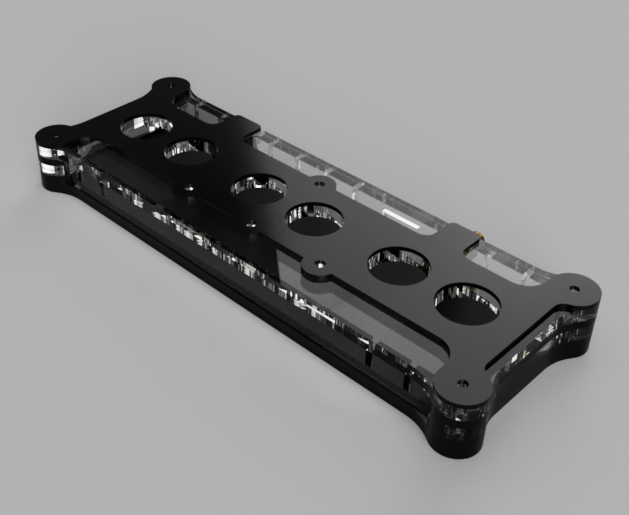
The enclosure design has been moved to Fusion 360. The files in the hardware folder are out of date and will be removed at some point.
The code was built on Ubuntu 16.04. The STM32Cube F3 library V1.9.0 will need to be installed to the /opt/ directory. The following apt packages are required.
cmake
gcc-arm-none-eabi
gdb-arm-none-eabi
To build the code.
mkdir firmware/nixie-clock/release
cd firmware/nixie-clock/release
cmake -DSTM32_CHIP=STM32F302C8 -DCMAKE_TOOLCHAIN_FILE=../../cmake/gcc_stm32.cmake -DSTM32Cube_DIR=/opt/STM32Cube_FW_F3_V1.9.0/ -DCMAKE_BUILD_TYPE=Release ..
make
To build for debugging.
mkdir firmware/nixie-clock/debug
cd firmware/nixie-clock/debug
cmake -DSTM32_CHIP=STM32F302C8 -DCMAKE_TOOLCHAIN_FILE=../../cmake/gcc_stm32.cmake -DSTM32Cube_DIR=/opt/STM32Cube_FW_F3_V1.9.0/ -DCMAKE_BUILD_TYPE=Debug ..
make| Qty | Value | Footprint | References |
|---|---|---|---|
| 12 | 10k | Resistors_SMD:R_0805 | R4, R8, R9, R10, R11, R12, R13, R14, R18, R24, R26, R29 |
| 9 | DDTD113ZC | TO_SOT_Packages_SMD:SOT-23 | Q1, Q2, Q3, Q4, Q5, Q7, Q8, Q9, Q10 |
| 8 | 0.1u | Capacitors_SMD:C_0603 | C1, C3, C7, C8, C10, C13, C14, C20 |
| 6 | LED_BGR | radio-clock:PLCC-6 | D1, D2, D3, D4, D5, D6 |
| 6 | TP | Measurement_Points:Measurement_Point_Round-TH_Small | TP1, TP2, TP3, TP4, TP5, TP6 |
| 4 | SW_Push | Buttons_Switches_ThroughHole:SW_PUSH_6mm | SW1, SW2, SW3, SW4 |
| 3 | 1.05k | Resistors_SMD:R_0805 | R1, R5, R15 |
| 3 | 2.43k | Resistors_SMD:R_0805 | R2, R6, R16 |
| 3 | 499 | Resistors_SMD:R_0805 | R3, R7, R17 |
| 2 | 0.01u | Capacitors_SMD:C_0603 | C11, C17 |
| 2 | 16p | Capacitors_SMD:C_0603 | C12, C16 |
| 2 | 1u | Capacitors_SMD:C_0805 | C9, C15 |
| 2 | 274 | Resistors_SMD:R_0805 | R25, R27 |
| 2 | 3.3u | Capacitors_ThroughHole:CP_Radial_D6.3mm_P2.50mm | C5, C6 |
| 2 | 5p | Capacitors_SMD:C_0603 | C18, C19 |
| 2 | 681k | Resistors_SMD:R_1206 | R20, R21 |
| 2 | CONN_01X10 | radio-clock:8-188275-0 | J2, J3 |
| 2 | RED | Diodes_SMD:D_1206 | D8, D9 |
| 1 | 0.05 | Resistors_SMD:R_1206 | R19 |
| 1 | 1.5k | Resistors_SMD:R_0805 | R28 |
| 1 | 10.7k | Resistors_SMD:R_1206 | R22 |
| 1 | 100u | radio-clock:DO3316P | L1 |
| 1 | 10u | Capacitors_SMD:C_0805 | C2 |
| 1 | 150u | Capacitors_ThroughHole:CP_Radial_D6.3mm_P2.50mm | C4 |
| 1 | 255k | Resistors_SMD:R_1206 | R23 |
| 1 | 3.7V LION | radio-clock:S8411-45R | BT1 |
| 1 | 32.768kHz | radio-clock:ABS07 | Y2 |
| 1 | 36.5k | Resistors_SMD:R_0805 | R30 |
| 1 | 8MHz | Crystals:Crystal_SMD_HC49-SD | Y1 |
| 1 | BARREL_JACK | radio-clock:PJ-002AH-SMT-TR | J1 |
| 1 | CONN_02X05 | radio-clock:TC2050-IDC | J5 |
| 1 | FDB14N30TM | TO_SOT_Packages_SMD:TO-263-2 | Q6 |
| 1 | FERRITE | Resistors_SMD:R_0805 | L2 |
| 1 | FGPMMOPA6H | radio-clock:FGPMMOPA6H | U4 |
| 1 | Fuse | radio-clock:01110501Z | F1 |
| 1 | LD1117S33TR | TO_SOT_Packages_SMD:SOT-223 | U1 |
| 1 | MAX1771 | Housings_SOIC:SOIC-8_3.9x4.9mm_Pitch1.27mm | U2 |
| 1 | MMBT2222A | TO_SOT_Packages_SMD:SOT-23 | Q11 |
| 1 | MURS140 | Diodes_SMD:D_SMB_Standard | D7 |
| 1 | SMA | Connect:SMA_THT_Jack_Straight | J6 |
| 1 | STM32F302C | Housings_QFP:LQFP-48_7x7mm_Pitch0.5mm | U3 |
| 1 | SW_Push | radio-clock:TL1105SF160Q | SW5 |
| 1 | USB_OTG | radio-clock:10118192 | J4 |
The 97 most common of 106 parts.


korken89/trustflight_hardware
A small and simple flight controller to be used with the trustflight firmware flight controller firmware, which is focusing on safety by using the Rust programming language.

alexcwu1121/hammerhead-turret-controller
To build: 1. Install Podman >4.x 2. Install VSCode 3. Install VSCode Dev Containers extension 4. In Dev Containers settings, set the following: - Docker Path: podman - Docker Compose Path: podman-compose - Docker…


dm2lct/tlnixie
PCB files for the Turmlabor nixie clock 2.0


DanielHeEGG/Nixie-Controller-v2
Second generation universal nixie clock controller

wheeler-microfluidics/kicad___hv_power_supply
Digitally adjustable high-voltage power supply
It measures 176 × 55 mm and has 2 copper layers, 1.6 mm thick.
106 parts, built around the STM32F302CBT6, MAX1771CPA+, LD1117S33TR(MS) and DDTD113ZC. The full list of its parts is on this page, with links to each part's symbol and footprint where PCBKit's library has them.
From the jeffkub/nixie-clock repository on GitHub, at the commit this page was made from: the board is hardware/main-board/main-board.kicad_pcb. PCBKit opens the board in the browser, with nothing to install.
Its repository publishes it under the MIT licence: you may reuse it on that licence's terms (keep the author's notice, and for a copyleft licence share your changes alike).