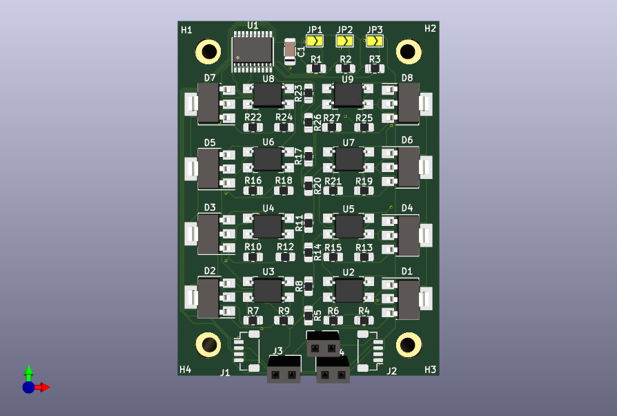
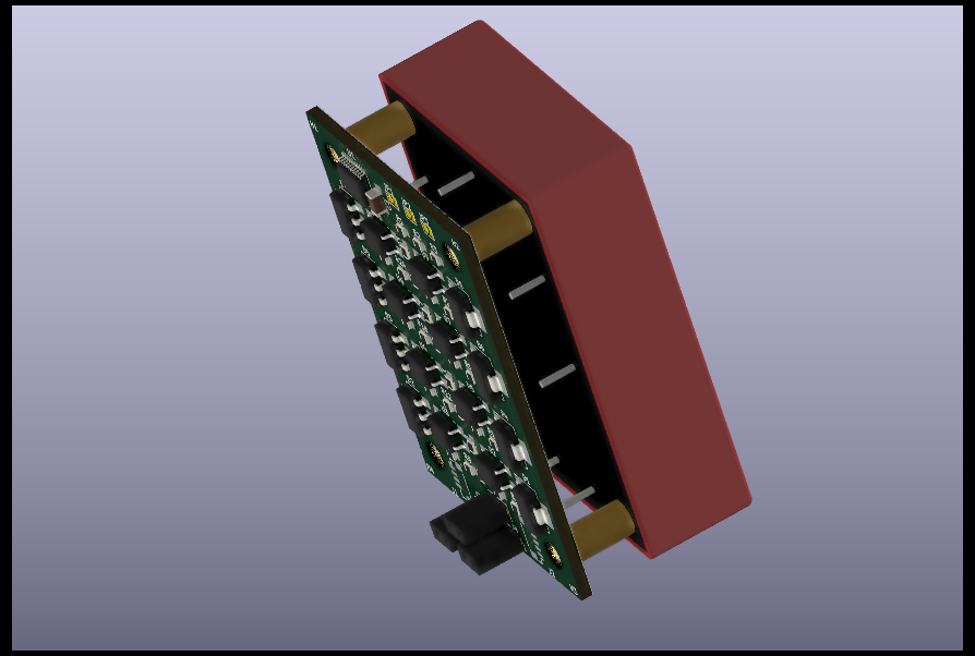
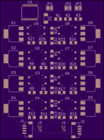
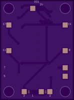
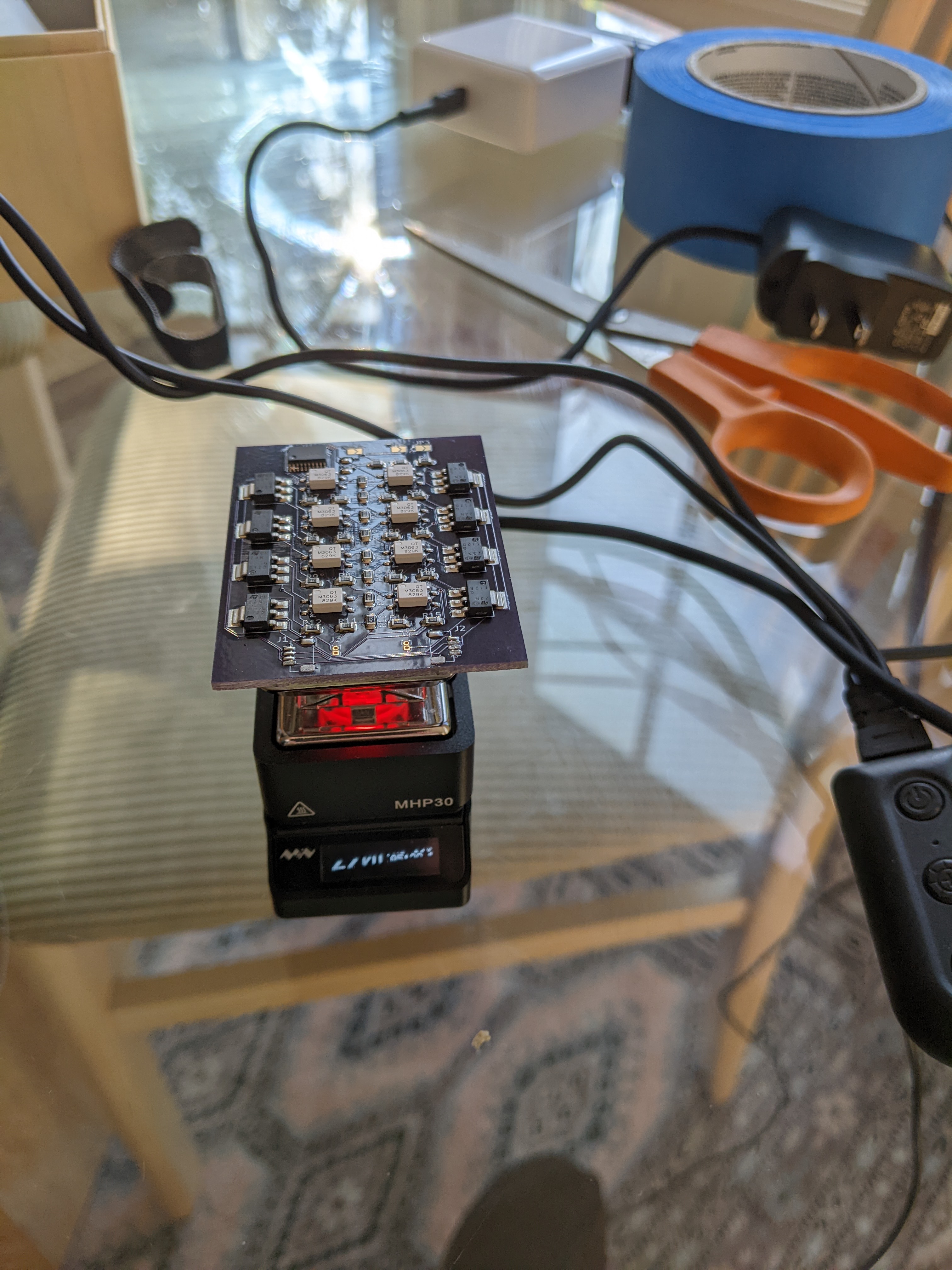
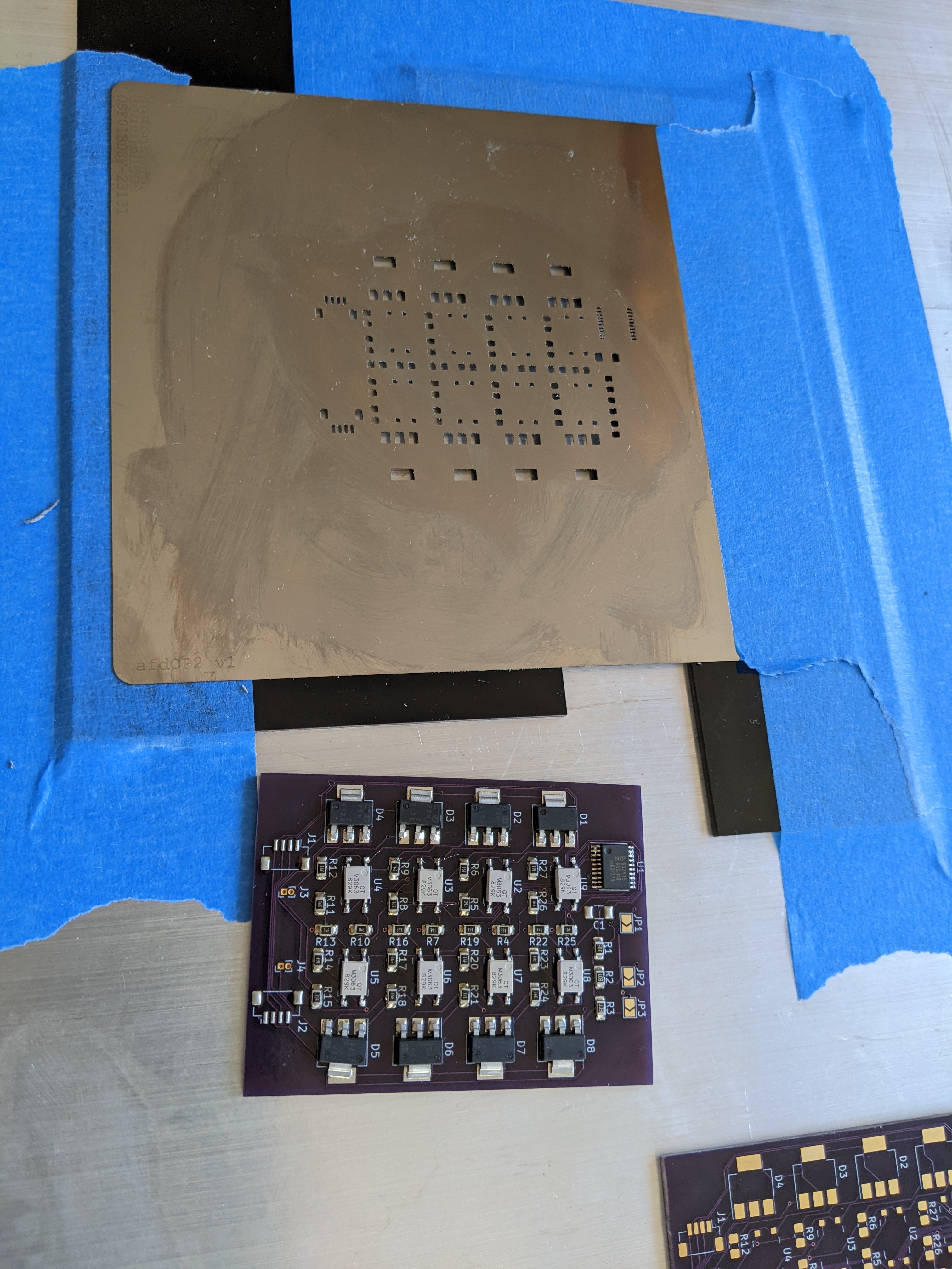
AfdDriver2Layer
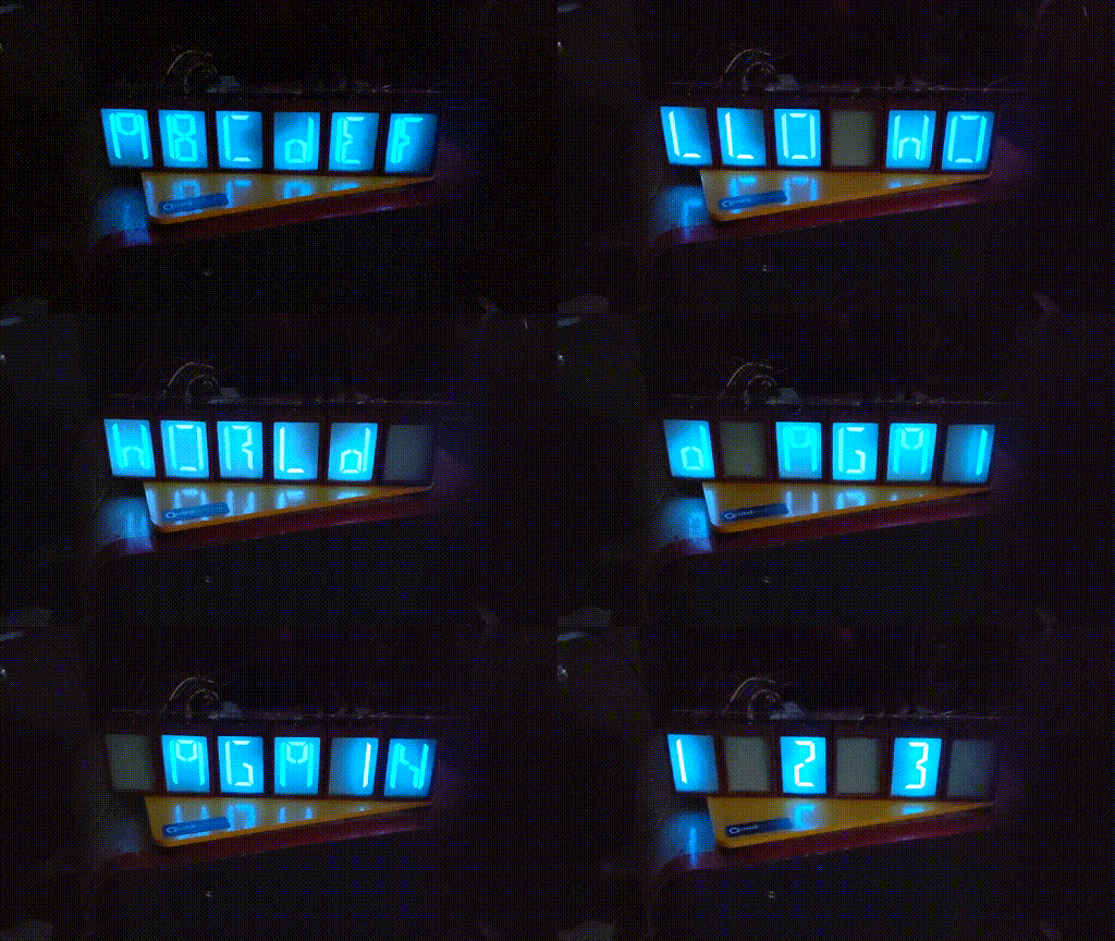
Display made of six eight-segment EL display units
- Size
- 43.2 × 58.4 mm
- Copper layers
- 2
- Thickness
- 1.6 mm
- Parts
- 53
- Nets
- 49
- Pads
- 172
- Tracks, vias
- 554, 36
- Pours
- 5
- Routed
- Yes
- KiCad
- KiCad 5 (file 20171130)
- Created
- 10 Nov 2021
- Updated
- 9 Sep 2025
Overview
AfdDriver2Layer is an open-source printed circuit board by jduanen, from the jduanen/alienFontDisplay repository on GitHub, published under the MIT licence. It is a 2-layer board of 43.2 × 58.4 mm with 53 parts on 49 nets, routed with 554 tracks and 36 vias.
It is built around the Z0103MN, PCF8574TS/3 and QTM3063T1. Its parts include 27 resistors, 9 ICs, 8 diodes, 4 connectors and 1 capacitor. It belongs with the lEDs and displays boards of this library.
Main components
3Z0103MN
SOT-223-40℃~+125℃@(Tj) 1.3V 10mA 1A 3mA 600V 8A@60Hz SOT-223 Thyristors (SCR)/Modules ROHSonsemiThyristors (SCR)/ModulesPCF8574TS/3
SSOP-20-4.4mm-40℃~+85℃ 100kHz 10mA 2.5V~6V 2.5uA 300uA 8 8 I2C Interrupt Output Reset function、Cascading and address extension、Built-in LED driver SSOP-20-4.4mm I/O Expanders ROHSNXP SemiconductorsI/O ExpandersQTM3063T1
MiNi-4-FLATTriac, SCR Output OptoisolatorsQT Brightek
README
README.mdalienFontDisplay
Display made of six eight-segment EL display units with per-display custom driver board and controller.
Scrolling display board that displays whatever string is published on a given MQTT channel over WiFi.

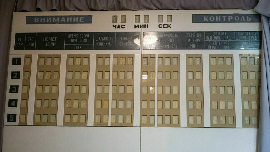
These displays were used in Russian tanks and missile launch consoles.

TBD
- Design 225VAC 400Hz inverter that can supply ?mA (?W)
- BOM
- WiFi interface board
- Firmware
- Tests
- Example code
- Documentation
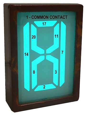
Display Pinout

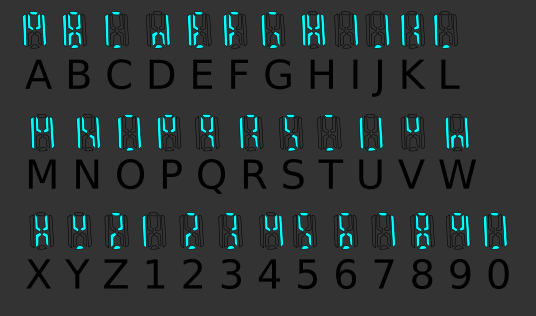
Alphanumeric Font

Single Display and Driver Board

Driver PCB

Schematic
EL Displays
IEL-O-VI C63.396.208-02
- Blue, Alien Font, Russian/Soviet Electroluminescent Display
- [0-9] and [A-Z] (after a fashion)
- some characters are lower case and some are missing strokes
- in particular, there isn't a center vertical stroke, so "T" and "I" are not so great
- seems to have been designed for Cyrillic characters
- some characters are lower case and some are missing strokes
- pinout
- 1: common
- 2: bottom horizontal (S)
- 3: bottom right angled (M)
- 5: n/c?
- 7: left vertical (L)
- 8: bottom left angled (M)
- 11: top right angled (M)
- 14: left vertical (L)
- 17: top horizontal (S)
- 20: top left angled (M)
- per-segment capacitance (estimates)
- S (2x): 55 pFd
- M (4x): 90 pFd
- L (2x): 170 pFd
Power Supply Design
- Specs
- 220VAC @ 400Hz
- 0.5-3mA per display
- four displays: 12mA (max)
- six displays: 18mA (max)
- Design alternatives
- drive audio amp into (CT?) step-up transformer
- DC boost converter into H-Bridge
=========================
-
notes
- ~200V @ 400Hz
- not squarewave -- filter or triangle wave for constant dv/dt
- less bright at 50Hz, but last longer
- need current limiting resistor if power source has low internal resistance
- e.g., 330K ohm @ 220V @ 50Hz
- 500 Hrs lifespan
- sine/square voltage up to 250V and 400Hz-5KHz
- decay time fractions of msec
- at least 6usec pulse
- no loss of brightness in pulses of 100usec at constant duty cycle
- most of drop in brightness occurs in first 200 hours of operation
- relatively flat after that
- for best lifetime, maintain constant frequency and reduce voltage
- use current limiting resistor for supplies with internal resistance less than 1Kohm
- add 0.03-0.05ufd caps in parallel with electrodes to improve reliability
- nomenclature
- I: indicator
- EL: electroluminescent
- color
- O: one color
- M: multicolor
- P: raster
- size (13x sizes)
- VI: 34x40mm
- II: 13x35mm
- IV: 18x26mm
- number of dots indicate brightness
- IEL-0-VI-101-246: 19x segment starburst with bar above and left and right commas
- constant power mode
- 220V @ 400Hz
- constant brightness mode
- 175-250V @ 1200Hz -- increases with service life
- 0.5-3 mA current
- DC will destroy the display
- can't multiplex displays -- need driver for each segment
- lifetime drops rapidly with supply frequency >400Hz
-
Links
- https://www.nixology.uk/el-displays/
- http://www.155la3.ru/electroluminescent.htm?fbclid=IwAR3kzInl6R3qaqCM56aDhy-eqRuBEZQ2xA1R94jkRoaB9Y2xDsH_GoB88GI
- https://www.youtube.com/watch?v=p6mNbgtnFK8
- http://lampes-et-tubes.info/cd/cd143.php?l=e
- http://www.nedopc.org/forum/viewtopic.php?f=65&t=11093
- https://www-nedopc-org.translate.goog/forum/viewtopic.php?f=65&t=11093&_x_tr_sch=http&_x_tr_sl=auto&_x_tr_tl=en&_x_tr_hl=en-US&_x_tr_pto=wapp
-
Sparkfun EL Inverter (COM-10469 retired)
- input: 12VDC
- output: 70-110V (90V typ)
- frequency: 800-3500Hz (2000Hz typ)
-
Sparkfun EL Inverter (sourced from Amazon)
- input: 5VDC
- output: 225VAC (in afd circuit)
- frequency: 5-7KHz (in afd circuit)
=======================================================================================
-
SmartSocket for Alien Font displays
- use same protocol on daisy-chained 9600 baud RS232 (3v3?)
- build single-sided PCB that fits on back of display units
- drive each segment individually
- use common HV PSU
- use circuits from SparkFun boards as they have been tested and shown to work
- need to select a PIC to use as the on-board controller
- PIC18F16Q41: same as PIC18F16Q40 but has an opAmp
- PIC18F16Q40:
- 14pin device has six GPIOs on PortA and another six on PortC
- has 1/2 UARTs
- 64KB program FLASH, 4KB SRAM, 512B EEPROM
- 18x GPIO, 2/3x 8b timers, 17x channels of 12b ADC, 2x 8b DACs, 4x DMA
- 32b CRC with scanner, vectored interrupts, temperature indicator, NCO, PWM/CCP
- C compiler
- CCS: http://www.ccsinfo.com -- $200-$500
- Hi-Tech: http://www.htsoft.com -- bought by Microchip
- Microchip: http://www.microchip.com -- free student mode
- MPLAB C18: microchip
- MikroC: free student version with limits
- https://www.microchip.com/en-us/development-tool/C18
- $1.5 at Mouser (in stock)
- example: https://github.com/microchip-pic-avr-examples/pic18f16q40-quadrature-decoder
- RA2: UART Tx programmer?
- RB7: UART Tx
- RB5: UART Rx
- RB4, RB6, RA4, RA5, RC0-RC7: GPIO
- PPS re-mappable input signals can be moved from default locations to other ports
- UART outputs: DTR1, RTS1, TX1, DTR2, RTS2, TX2, DTR3, RTS3, TX3
- UART inputs: RX1, CTS1, RX2, CTS2, RX3, CTS3
- pin allocation table (default)
- RB5: RX1
- RB7: CTS1
- RC1: RX2
- RC2: CTS2
- RC3: RX3
- RC5: CTS3
- use shift registers?
- use I2C port expander?
-
display unit dimensions, pin and threaded spacer locations are not consistent across instances
-
Use SparkFun EL boards for proof of concept testing
-
EL Sequencer v23
- https://www.sparkfun.com/products/12781
- http://cdn.sparkfun.com/datasheets/Components/EL/SparkFun_EL_Sequencer_v23.pdf
- ATMega328P processor on-board
- use "Arduino Duemilanove or Diecimila" board with FTDI USB dongle
- Gets HV from Sparkfun EL Inverter
- not ideal -- need higher voltage and better frequency
- Drives HV to all segments of all displays
- EL Escudo Dos pulls display commons to HV_GND
- D2-D9 used to drive EL_A-EL_H
- EL_A: pin 2
- EL_B: pin 3
- EL_C: pin 7
- EL_D: pin 8
- EL_E: pin 11
- EL_F: pin 14
- EL_G: pin 17
- EL_H: pin 20
- Sends six (active high) TTL signals to EL Escudo Dos to enable each display
- ADC_0 (JP4:2): display #1
- ADC_1 (JP4:7): display #2
- ADC_2 (JP2:8): display #3
- ADC_3 (JP2:7): display #4
- ADC_4 (JP2:6): display #5
- ADC_5 (JP2:5): display #6
-
EL Escudo Dos
- https://www.sparkfun.com/products/10878
- https://cdn.sparkfun.com/datasheets/Components/EL/EL_Escudo_Dos/EL%20Escudo%20Dos%20v21.pdf
- Pulls display common lines (pin 1) down to HV_GND
- EL_H: display #1 ... EL_C: display #6
- gets HV_GND and TTL display unit selector signals from EL Sequencer
- all SCRs have common HV connected to their tabs
- and they have individual outputs to load and ground
- need to cut HV to tabs and connect them to the display common signals
- and short all load outputs to HV_GND
-
misc
- mqtt listener
- mosquitto_sub -t /displays/# -F "%I,%t,%p"
- commands
- rssi
- version
- reset
- rate[=]
- scrollDelay[=]
- pause[=]
- display[=]
- e.g., mosquitto_pub -t "/displays/afd//cmd" -m "display=abcdefghijklmnopqrstuvwxyz0123456789"
- mqtt listener
Parts
53| Qty | Value | Footprint | References |
|---|---|---|---|
| 24 | 390 | Resistor_SMD:R_0805_2012Metric_Pad1.20x1.40mm_HandSolder | R10, R11, R12, R13, R14, R15, R16, R17, R18, R19, R20, R21, R22, R23, R24, R25 +8 |
| 8 | QTM3063T1 | jdn_library:4-SMD_3.8x4.6mm | U2, U3, U4, U5, U6, U7, U8, U9 |
| 8 | Z0103MN | Package_TO_SOT_SMD:SOT-223 | D1, D2, D3, D4, D5, D6, D7, D8 |
| 3 | 10K Ohm | Resistor_SMD:R_0805_2012Metric_Pad1.20x1.40mm_HandSolder | R1, R2, R3 |
| 2 | HighVoltageAC | Connector_PinHeader_1.00mm:PinHeader_1x02_P1.00mm_Vertical | J3, J4 |
| 2 | Qwiic_Connector | Connector_JST:JST_SH_BM04B-SRSS-TB_1x04-1MP_P1.00mm_Vertical | J1, J2 |
| 1 | 0.1 uFd | Capacitor_SMD:C_1206_3216Metric_Pad1.33x1.80mm_HandSolder | C1 |
| 1 | ADDR0 | Jumper:SolderJumper-2_P1.3mm_Open_TrianglePad1.0x1.5mm | JP1 |
| 1 | ADDR1 | Jumper:SolderJumper-2_P1.3mm_Open_TrianglePad1.0x1.5mm | JP2 |
| 1 | ADDR2 | Jumper:SolderJumper-2_P1.3mm_Open_TrianglePad1.0x1.5mm | JP3 |
| 1 | IEL-O-VI_C63.396.208-02_SMD | jdn_library:C63.396.208-02_SMD | DS1 |
| 1 | PCF8574TS | Package_SO:SSOP-20_4.4x6.5mm_P0.65mm | U1 |
Questions
How big is the AfdDriver2Layer PCB?
It measures 43.2 × 58.4 mm and has 2 copper layers, 1.6 mm thick.
What parts does the AfdDriver2Layer use?
53 parts, built around the Z0103MN, PCF8574TS/3 and QTM3063T1. The full list of its parts is on this page, with links to each part's symbol and footprint where PCBKit's library has them.
Where can I download the AfdDriver2Layer KiCad files?
From the jduanen/alienFontDisplay repository on GitHub, at the commit this page was made from: the board is board/afdDriverOP2/afdDriver2Layer.kicad_pcb and its schematic board/afdDriver/afdDriver.kicad_sch. PCBKit opens the board in the browser, with nothing to install.
Can I use the AfdDriver2Layer design in my own project?
Its repository publishes it under the MIT licence: you may reuse it on that licence's terms (keep the author's notice, and for a copyleft licence share your changes alike).
More from jduanen/alienFontDisplay
2- 2 layers43.2 × 58.4 mm

- 2 layers

Similar boards
- 2 layers101.6 × 101.6 mm

ARDUINO PLC
Reiken3099/ArduPLC
PCB designs made with the purpose of using both Arduino hardware and software in an industrialized way adapting said hardware for said purpose. These designs are made in KICAD free software
92 parts1CC0-1.0 - 4 layers94.5 × 99.8 mm

ValveController
afewyards/HydroMix
A mains-powered, Zigbee-connected controller for a hydronic 3-way mixing valve — it regulates the supply-water temperature of a floor heating/cooling system and keeps regulating autonomously if the Zigbee link goes down.
123 partsMIT - 4 layers55.2 × 76.5 mm

- 4 layers173.9 × 93.4 mm

Z3660 v022
shanshe/Z3660
Amiga 4000 CPU accelerator board based on A3660 and Z-turn FPGA board
198 parts78GPL-3.0 - 4 layers70 × 90 mm

- 2 layers101.6 × 76.2 mm

I2CMultiplexer
freudenthal/I2CTCA9548Multiplexer
An I2C multiplexer using a TCA9548 and a PCF8574 for interrupt.
110 parts - 2 layers57.1 × 76.2 mm

- 2 layers165.1 × 88.9 mm