
2 layers91.4 × 99.1 mm

 jdesbonnet/RFMxx_LPC812_PCB4
PCB board to experiment with HopeRF RFM69 and RFM98 radio modules. Uses ARM Cortex-M0+ LPC812 as controller.
LPC824 RFM9x is an open-source printed circuit board by jdesbonnet, from the jdesbonnet/RFMxx_LPC812_PCB repository on GitHub. It is a 2-layer board of 38.9 × 16.5 mm with 16 parts on 27 nets, routed with 221 tracks and 28 vias.
It is built around the LPC824M201JDH20. Its parts include 3 ICs, 3 connectors, 2 capacitors, 1 resistor and 1 diode. It belongs with the NXP (LPC, Kinetis, i.MX RT) boards of this library.
The V2 series replaces the LPC812 with LP824, and adds a SPI flash IC.
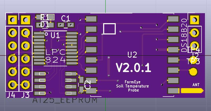
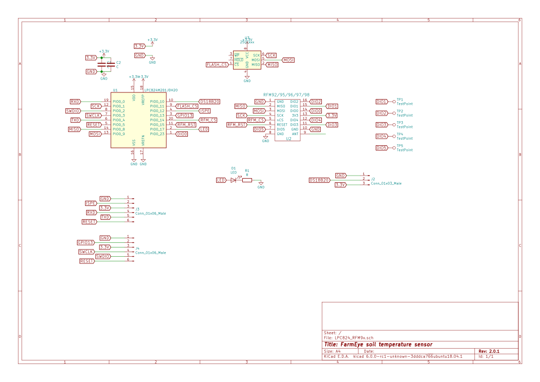
Improvement on 2014 design: more compact board.
V2.0.1 board arrived back from OSHPark on 2018-05-11.
(from top to bottom in the redering above)
J3: GND, ISPE, 3.3V, RXD, TXD, RESET
J4: GND, GPIO13, 3.3V, SWCLK, SWDIO, RESET
SPI bus is shared with RFM module and flash IC. Flash IC is 25P16 (or any SPI flash with similar pinout).
| Function | Pin | |
|---|---|---|
| FLASH_CS | PIO0_11 | This is a hardware bug: PIO0_11 is open drain: cannot drive high w/o external pullup R |
| MOSI | PIO0_9 | |
| MISO | PIO0_8 | |
| SCK | PIO0_1 | |
| RFM_CS | PIO0_14 | |
| RFM_RST | PIO0_15 | |
| LED | PIO0_17 | |
| RFM_DIO0 | PIO0_23 | |
| DS18B20 | PIO0_10 |
Temporary fix for FLASH_CS bug is to route GPIO0_13 from J4 with bodge wire. An alternative approach would be to glue SMD R for pull up to back of PCB. Will shuffle the pins in next PCB to that PIO0_11 is used only for input. Also may have problem with PIO0_10 used for the DS18B20.
DS18B20 confirmed to work. A 0603 4.7K SMD R is soldered between the 3.3V and data on J2. 0603 is about the perfect size for that hack. Unclear if this will have any impact of the deep sleep current consumption.
The external flash IC chosen has a deep-sleep current much larger than what can be achieved with the LPC824 on its own. Seeing something in the order of 20µA (vs 3µA from LPC824 in powerdown). However there are parts which claim much better deep sleep performance eg Macronix MX25R6435F which is pin compatible. http://www.macronix.com/en-us/products/NOR-Flash/Pages/Ultra-Low-Power-Flash.aspx
| Qty | Value | Footprint | References |
|---|---|---|---|
| 5 | TEST | Measurement_Points:Measurement_Point_Round-SMD-Pad_Small | TP1, TP2, TP3, TP4, TP5 |
| 2 | C | Capacitors_SMD:C_0603_HandSoldering | C1, C2 |
| 2 | Conn_01x06 | Pin_Headers:Pin_Header_Straight_1x06_Pitch2.54mm | J3, J4 |
| 1 | AT25_EEPROM | adafruit:SO08 | U3 |
| 1 | Conn_01x03 | Pin_Headers:Pin_Header_Straight_1x03_Pitch2.54mm | J2 |
| 1 | LED | LEDs:LED_0603_HandSoldering | D1 |
| 1 | LOGO | FarmEye:farmeye_logo_medium_BMask | G*** |
| 1 | LPC824M201JDH20 | TSSOP20_handsolder:TSSOP-20_4.4x6.5mm_Pitch0.65mm | U1 |
| 1 | R | Resistors_SMD:R_0603_HandSoldering | R1 |
| 1 | RFM92/95/96/97/98 | RF_Modules:Hopref_RFM9XW_SMD | U2 |

jdesbonnet/PCB_LPC824M201JDH20_breakout
Breakout board PCB for LPC824 in TSSOP20 package (LPC824M201JDH20, LPC822M101JDH20)


Squantor/squantorDevelBoards
Various development boards/test for microcontrollers, check for breakouts here

google/mozc-devices
Circuit diagrams and firmware source code for Gboard DIY keyboards

conorpp/u2f-zero
U2F USB token optimized for physical security, affordability, and style

rusefi/rusefi
rusefi - GPL internal combustion engine control unit

VoronDesign/Voron-Hardware
Cool Hardware designed by the Voron Design group
It measures 38.9 × 16.5 mm and has 2 copper layers, 1.6 mm thick.
16 parts, built around the LPC824M201JDH20. The full list of its parts is on this page, with links to each part's symbol and footprint where PCBKit's library has them.
From the jdesbonnet/RFMxx_LPC812_PCB repository on GitHub, at the commit this page was made from: the board is RFM98LPC824/LPC824_RFM9x.kicad_pcb. PCBKit opens the board in the browser, with nothing to install.
Its repository states no licence, so its author keeps all rights: ask jdesbonnet before reusing the design.