
10 layers224.5 × 160 mm
Haasoscope pro adc fpga board
drandyhaas/HaasoscopePro
Affordable 2 GHz 3.2 GS/s 12 bit open-source open-hardware expandable USB real-time oscilloscope
586 parts485MIT

 jchik1102/Agro-PCB
Native KiCad schematic and four-layer PCB draft for a regulated 12 V input with separate 5 V and 3.3 V buck converters. Designed as a documented portfolio project; not a fabrication release or tested hardware.
Agrobot Power Board is an open-source printed circuit board by jchik1102, from the jchik1102/Agro-PCB repository on GitHub. It is a 4-layer board of 96 × 78 mm with 41 parts on 16 nets, routed with 297 tracks and 42 vias.
It is built around the LMR33630ADDA. Its parts include 17 capacitors, 4 resistors, 3 connectors, 2 ICs and 2 diodes.
Native KiCad schematic and four-layer PCB draft for a regulated 12 V input with separate 5 V and 3.3 V buck converters. Designed as a documented portfolio project; not a fabrication release or tested hardware.
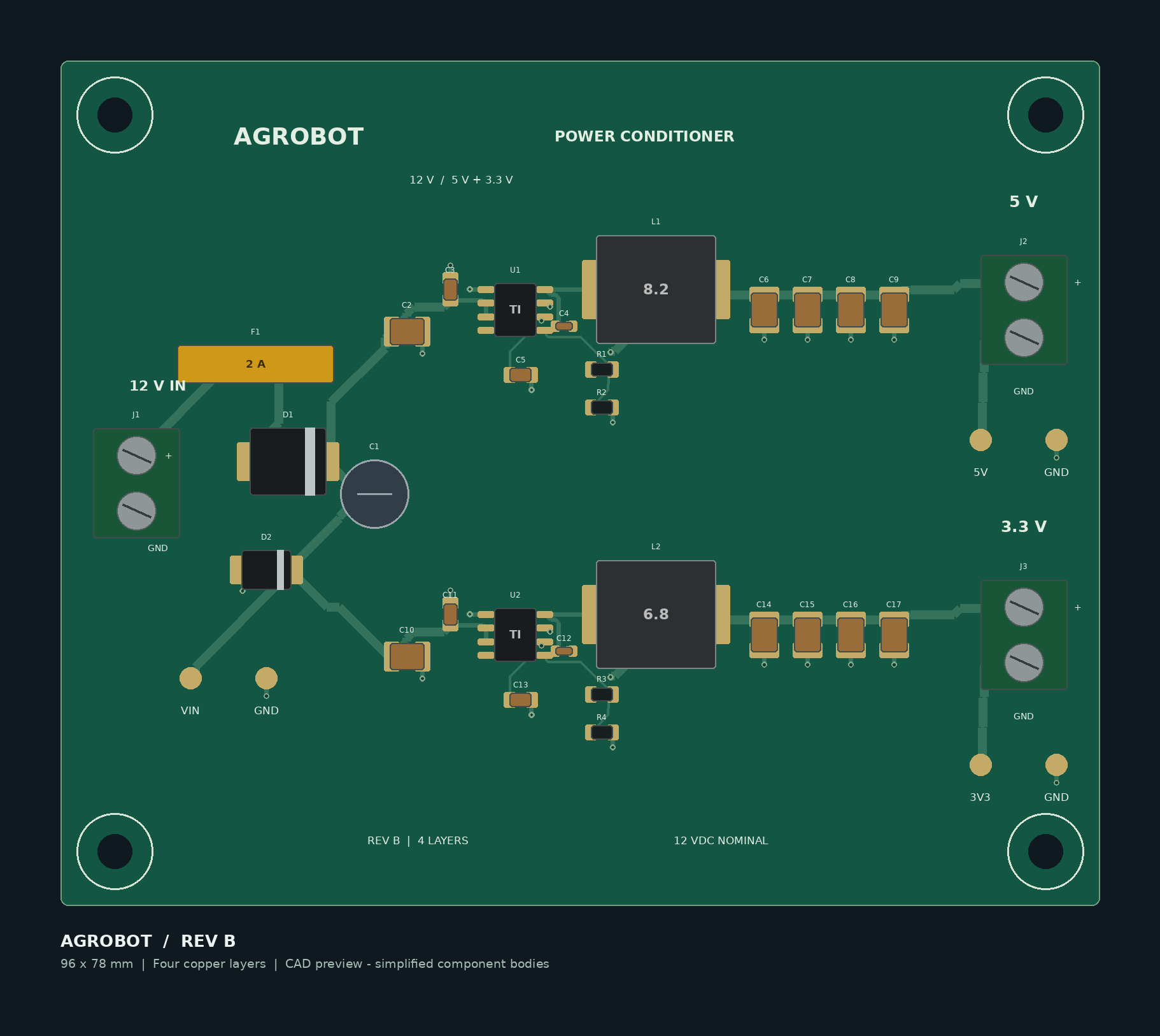
Agrobot_Power_Board.kicad_pro in KiCad.Ground zones have been defined but are delivered unfilled. Until step 5, ground connections will appear incomplete. The supplied images and PDF are authoring previews, not screenshots or exports from KiCad.
| Item | Target / implementation | Evidence status |
|---|---|---|
| Input | Regulated 12 V DC, screw terminal | Nominal design input; not qualified for battery/automotive transients |
| 5 V output | 0.75 A continuous, 1.5 A peak | Design target; load and thermal testing pending |
| 3.3 V output | 0.5 A continuous, 1.0 A peak | Design target; load and thermal testing pending |
| Ripple | 20 mVpp / 10 mVpp respectively, 20 MHz bandwidth | Targets only; not simulated or measured |
| Protection | Resettable input fuse, reverse-polarity diode, TVS clamp | Component-level proposal; coordination review pending |
| Board | 96 x 78 mm, four copper layers, four 3.2 mm mounting holes | Native layout draft |
| Ground | Two internal planes plus outer-layer zones | Fill locally before native DRC |
The two LMR33630 converters use separate inductors, feedback networks, and output capacitors. No microcontroller or sensors are included: this is the Agrobot power-conditioning board only. Peak duration is unspecified; no guaranteed peak-duration capability is claimed.
.kicad_pro, .kicad_sch, .kicad_pcb: editable native project.Libraries: project-local symbols, footprints, simplified 3D models.Documentation/Schematic_Preview.pdf: immediately viewable schematic preview.Images: illustrative top-board preview.Upload this folder's contents after reviewing the design. Keep the libraries and relative folder structure intact. The included .gitignore excludes local report runs and editor backups. You can deliberately add selected native PDFs, renders, and reviewed reports later.
An accurate project description is: "Developed a KiCad power-conditioning PCB draft for a 12 V input and 5 V/3.3 V outputs, with input protection and documented load/ripple targets. Fabrication and bench validation pending."
Do not describe the ripple or current targets as measured results, or this project as completed in Altium. AI-assisted authoring should be described accurately when relevant to portfolio or academic requirements.
| Qty | Value | Footprint | References |
|---|---|---|---|
| 8 | 22u / 16 V | Agrobot:C1210 | C6, C7, C8, C9, C14, C15, C16, C17 |
| 4 | M3 / NPTH | Agrobot:Hole | H1, H2, H3, H4 |
| 3 | GND | Agrobot:TP | TP4, TP5, TP6 |
| 2 | 100k / 1% | Agrobot:R0805 | R1, R3 |
| 2 | 100n / 16 V | Agrobot:C0603 | C4, C12 |
| 2 | 10u / 50 V | Agrobot:C1210 | C2, C10 |
| 2 | 1u / 16 V | Agrobot:C0805 | C5, C13 |
| 2 | 220n / 50 V | Agrobot:C0805 | C3, C11 |
| 2 | LMR33630ADDA | Agrobot:DDA | U1, U2 |
| 1 | 12 V INPUT | Agrobot:Terminal | J1 |
| 1 | 15 V TVS | Agrobot:SMB | D2 |
| 1 | 2 A HOLD / 30 V | Agrobot:PTC | F1 |
| 1 | 24.9k / 1% | Agrobot:R0805 | R2 |
| 1 | 3.3 V OUTPUT | Agrobot:Terminal | J3 |
| 1 | 43.2k / 1% | Agrobot:R0805 | R4 |
| 1 | 47u / 50 V | Agrobot:Electro | C1 |
| 1 | 5 A / 60 V | Agrobot:SMC | D1 |
| 1 | 5 V OUTPUT | Agrobot:Terminal | J2 |
| 1 | 6.8u / shielded | Agrobot:Inductor | L2 |
| 1 | 8.2u / shielded | Agrobot:Inductor | L1 |
| 1 | OUT_3V3 | Agrobot:TP | TP3 |
| 1 | OUT_5V | Agrobot:TP | TP2 |
| 1 | VIN_PROT | Agrobot:TP | TP1 |
It measures 96 × 78 mm and has 4 copper layers, 1.6 mm thick.
41 parts, built around the LMR33630ADDA. The full list of its parts is on this page, with links to each part's symbol and footprint where PCBKit's library has them.
From the jchik1102/Agro-PCB repository on GitHub, at the commit this page was made from: the board is Agrobot_Power_Board.kicad_pcb and its schematic Agrobot_Power_Board.kicad_sch. PCBKit opens the board in the browser, with nothing to install.
Its repository states no licence, so its author keeps all rights: ask jchik1102 before reusing the design.
drandyhaas/HaasoscopePro
Affordable 2 GHz 3.2 GS/s 12 bit open-source open-hardware expandable USB real-time oscilloscope

jamarju/c64-psu
Efficient Commodore 64 power supply with overvoltage + overcurrent protection

Andre1Becker/GalvOS
Open-source ESP32-S3 laser show controller — built to replace proprietary OEM controllers in RGB galvo laser projectors

Coen-Lab/exp-control-board
Hardware and firmware for an experimental control board for scientific rigs

ErdemA33/stm32f405-flight-controller
Open-source ArduPilot-compatible flight controller for fixed-wing UAVs. STM32F405, 4-layer KiCad design, built in 5 modular stages.

lhr-solar/PS-MotorControllerInterfacePCB
Provides power conversion/protection and fan control for the Prohelion WaveSculptor 22 motor controller

kfilipekk/iridium_drone
STM32H743 flight controller that navigates without GPS from Iridium satellite Doppler

KareemOye/USB_POWER_SUPPLY_PCB
12 V to 5 V USB step-down supply based on the LM2596-ADJ, designed in KiCad