2 layers105 × 50 mm

 jboymel/piano-robot
Modular solenoid-based robotic piano actuator system — Northwestern SURG 2026
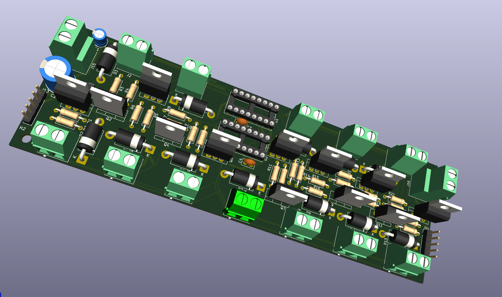
Solenoid driver v2 is an open-source printed circuit board by jboymel, from the jboymel/piano-robot repository on GitHub. It is a 2-layer board of 163.8 × 52.4 mm with 75 parts on 48 nets, routed with 512 tracks and 42 vias.
It is built around the 74HC595, FR307 and IRLZ44N, with the SMBJ28A among its other parts. Its parts include 24 resistors, 16 connectors, 13 diodes, 12 transistors and 4 capacitors. It belongs with the robots and motor control boards of this library.


A modular, clamp-on solenoid system that plays an acoustic piano from a MIDI score. Scaled from a one-octave prototype to a 7-octave (84-key) array of daisy-chained driver boards.
Northwestern University · Summer Undergraduate Research Grant (SURG) 2026 Jordan Boymel · Advisor: Dr. Brenna Argall, Assistive & Rehabilitation Robotics Lab, Shirley Ryan AbilityLab
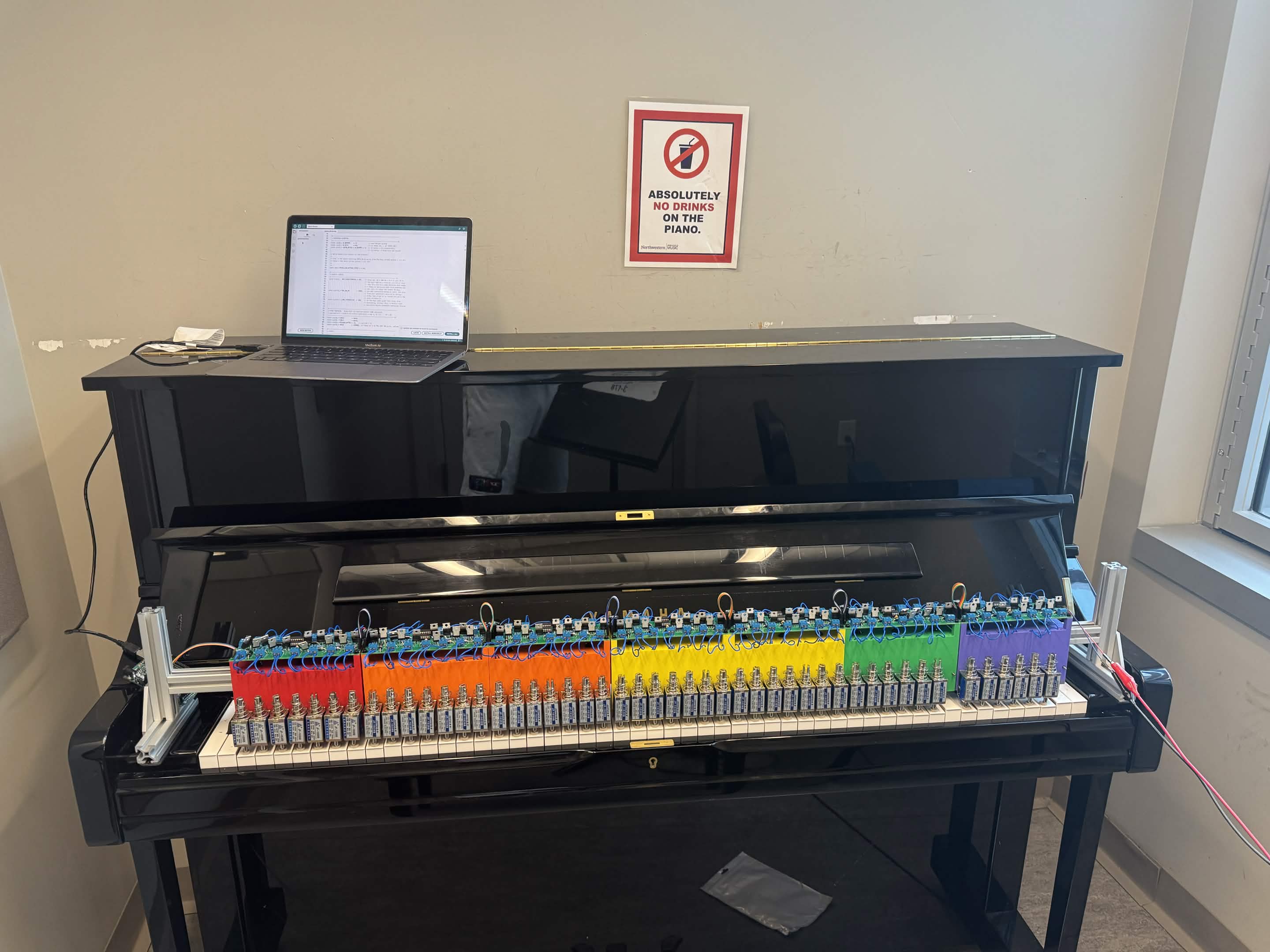
Status (Sept 2026): hardware, firmware, and host software complete; full-scale tuning paused. The whole pipeline, from MIDI to solenoids, runs. The final demo used a lower-rated 24 V supply because the main supply couldn't be wired properly, and several actuators strike inconsistently. See Current status and known issues.
Self-playing pianos are purpose-built, expensive instruments. This project asks whether a modular attachment can turn an ordinary piano into a music-making machine instead. It is motivated by making piano playing accessible to people with motor disabilities, and by the number of acoustic pianos that sit unused.
| Area | What it is |
|---|---|
| Driver electronics | Custom 2-layer KiCad PCB, one per octave: 12 low-side MOSFET channels, flyback protection, and a shift-register serial interface. Boards daisy-chain for power and signal. |
| Actuation | 24 V push-pull solenoids (one per key) with a threaded felt-tipped striker |
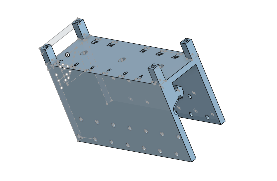
| Mechanical | Parametric Onshape bracket that straddles 80/20 T-slot extrusion over the keybed. Key pitch was measured on a real piano. |
| Firmware | Arduino Mega sketch that receives full keyboard state over USB serial and clocks it to the shift-register chain, with safety interlocks |
| Host software | Python player that reads a MuseScore MIDI export, compensates for actuator latency, and streams frames to the Arduino |
The Arduino connects to the whole 84-key array through five wires: 5 V, GND, DATA (pin 51), CLOCK (pin 52), and LATCH (pin 8).
| Field | Bytes | Value |
|---|---|---|
| Sync | 2 | 0xAA 0x55 |
| Key state | 11 | 84 bits, one per key (1 = energized) |
| Checksum | 1 | XOR |
Sent at 250000 baud. Every frame carries the full keyboard state. The Arduino never has to reconstruct note-on/note-off history, so a dropped frame is simply replaced by the next one.
| Limit | Value | Purpose |
|---|---|---|
MAX_SIMULTANEOUS | 20 keys | Caps solenoid current at about 8 A |
MAX_ON_MS | 5000 ms | Releases any key held too long, which protects the coils from overheating |
LINK_TIMEOUT_MS | 500 ms | Releases all keys if the host stops sending valid frames |
Measured strike latency is about 50 ms from energize to key contact. musescore_player.py schedules every note ATTACK_LATENCY_MS (≈50 ms) early so strikes land on the beat. It also enforces MINIMUM_STRIKE_HOLD_MS (≈10 ms) so very short notes still fully depress the key.
The latency also sets a mechanical limit: repeated notes on the same key top out around sixteenth notes at 95–100 BPM.
The project started as a one-octave bench prototype focused on characterizing a single key. The table lists the major changes on the way to 84 keys.
| Change | Why |
|---|---|
| One Arduino pin per key → 74HC595 shift-register chain | 84 keys can't each get a pin. Three signal lines now drive any number of boards. |
| IRLB8721 (30 V) → IRLZ44N (55 V) | More drain-voltage margin against inductive switching transients on a 24 V rail |
| 3-tier PCB stack → 2 tiers | The FSR circuit was confirmed as instrumentation only, not part of the production drive path |
| One large board → one PCB per octave, daisy-chained | Identical boards are cheaper to fabricate, easier to debug, and scale to any number of octaves |
| Key pitch 23.4 mm → ≈23.5 mm | Measured on a real piano. The error accumulates across an octave. |
Peer review of the schematics caught wiring errors before fabrication, including flyback diode polarity and MOSFET pinout.
Works
Resolved
Known issues
firmware/
  piano_driver/        piano_driver.ino: Arduino Mega sketch (serial → shift-register chain)
  bench_test/          serial_logger.py: logger from the single-key bench prototype
host/                  midi_player.py: MIDI file → serial key-state frames
hardware/
  pcb/                 KiCad project (solenoid-driver-v2) and fabrication Gerbers (.zip)
cad/
  stl/                 bracket.stl
matlab/analysis/       analyze_trials.m: trial statistics (onset time, force)
docs/                  BOM, wiring, schematic PDF, chain-failure write-up
media/                 Photos, KiCad render, test videos
matlab/analysis/analyze_trials.mgenerates placeholder data if no real trial CSV is present. Any plots it produces without real data are not results.
| Qty | Value | Footprint | References |
|---|---|---|---|
| 12 | 10kΩ | Resistor_THT:R_Axial_DIN0207_L6.3mm_D2.5mm_P10.16mm_Horizontal | R1, R3, R5, R7, R9, R11, R13, R15, R17, R19, R21, R23 |
| 12 | 220Ω | Resistor_THT:R_Axial_DIN0207_L6.3mm_D2.5mm_P10.16mm_Horizontal | R2, R4, R6, R8, R10, R12, R14, R16, R18, R20, R22, R24 |
| 12 | FR307 | Diode_THT:D_DO-201AD_P15.24mm_Horizontal | D2, D3, D4, D5, D6, D7, D8, D9, D10, D11, D12, D13 |
| 12 | IRLZ44N | Package_TO_SOT_THT:TO-220-3_Vertical | Q1, Q2, Q3, Q4, Q5, Q6, Q7, Q8, Q9, Q10, Q11, Q12 |
| 12 | Screw_Terminal_01x02 | TerminalBlock_Phoenix:TerminalBlock_Phoenix_MKDS-1,5-2-5.08_1x02_P5.08mm_Horizontal | J1, J2, J3, J4, J5, J6, J7, J8, J9, J10, J11, J12 |
| 4 | MountingHole | MountingHole:MountingHole_3.2mm_M3 | H1, H2, H3, H4 |
| 2 | 0.1µF | Capacitor_THT:C_Disc_D5.0mm_W2.5mm_P2.50mm | C3, C4 |
| 2 | 74HC595 | Package_DIP:DIP-16_W7.62mm_Socket | U1, U2 |
| 2 | Conn_01x05_Pin | Connector_PinHeader_2.54mm:PinHeader_1x05_P2.54mm_Vertical | J13, J14 |
| 2 | Screw_Terminal_01x02 | TerminalBlock_Phoenix:TerminalBlock_Phoenix_MKDS-3-2-5.08_1x02_P5.08mm_Horizontal | J15, J16 |
| 1 | 1000µF | Capacitor_THT:CP_Radial_D10.0mm_P5.00mm | C2 |
| 1 | 10µF | Capacitor_THT:CP_Radial_D5.0mm_P2.00mm | C1 |
| 1 | SMBJ28A | Diode_SMD:D_SMB | D1 |

jibonaronno/documentsA
It is required to change settings using SCLManager.exe when required for new setup.


cryptoAlgorithm/chess-printer
A chess bot, but on steroids. Custom 3D printer control board with a few oddly specific features.

locokepler/Pipe_Organ
The repository of the pipe organ, over the different iterations of mechanical, electrical, and code design

24bec124-sketch/IROC-U-Charging-NMOS
Developed for Team Arrow as part of IRoC-U (ISRO Robotics Challenge - URSC), a national student competition hosted by the Indian Space Research Organization (ISRO).
It measures 163.8 × 52.4 mm and has 2 copper layers, 1.6 mm thick.
75 parts, built around the 74HC595, FR307, IRLZ44N and SMBJ28A. The full list of its parts is on this page, with links to each part's symbol and footprint where PCBKit's library has them.
From the jboymel/piano-robot repository on GitHub, at the commit this page was made from: the board is hardware/pcb/solenoid-driver-v2.kicad_pcb and its schematic hardware/pcb/solenoid-driver-v2.kicad_sch. PCBKit opens the board in the browser, with nothing to install.
Its repository states no licence, so its author keeps all rights: ask jboymel before reusing the design.