4 layers45 × 29.2 mm
Pocket 2.66
quintenluyten2/Pocket_2.66_E-reader_PCB
PCB for 2.13" and 2.66" E-ink displays with ESP32-C3, micro-SD card, battery management, and 3 user buttons
88 parts3

 JBlitzar/hairtag3
homemade airtag
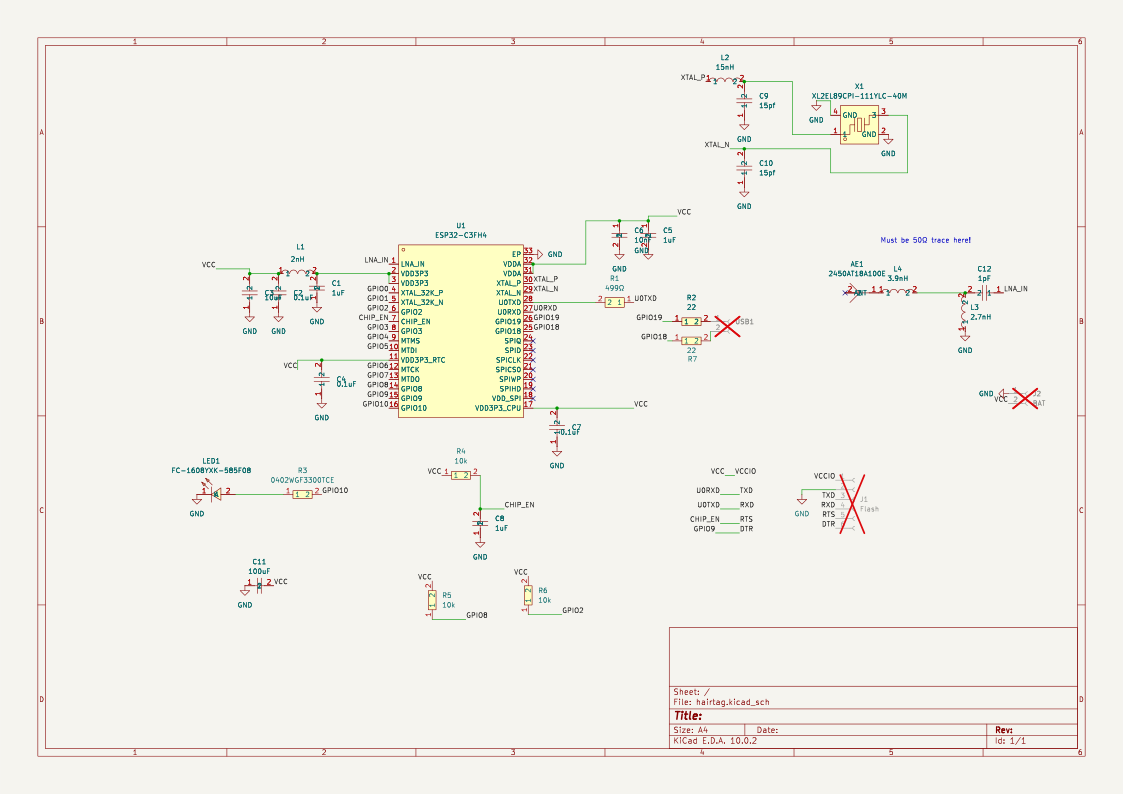
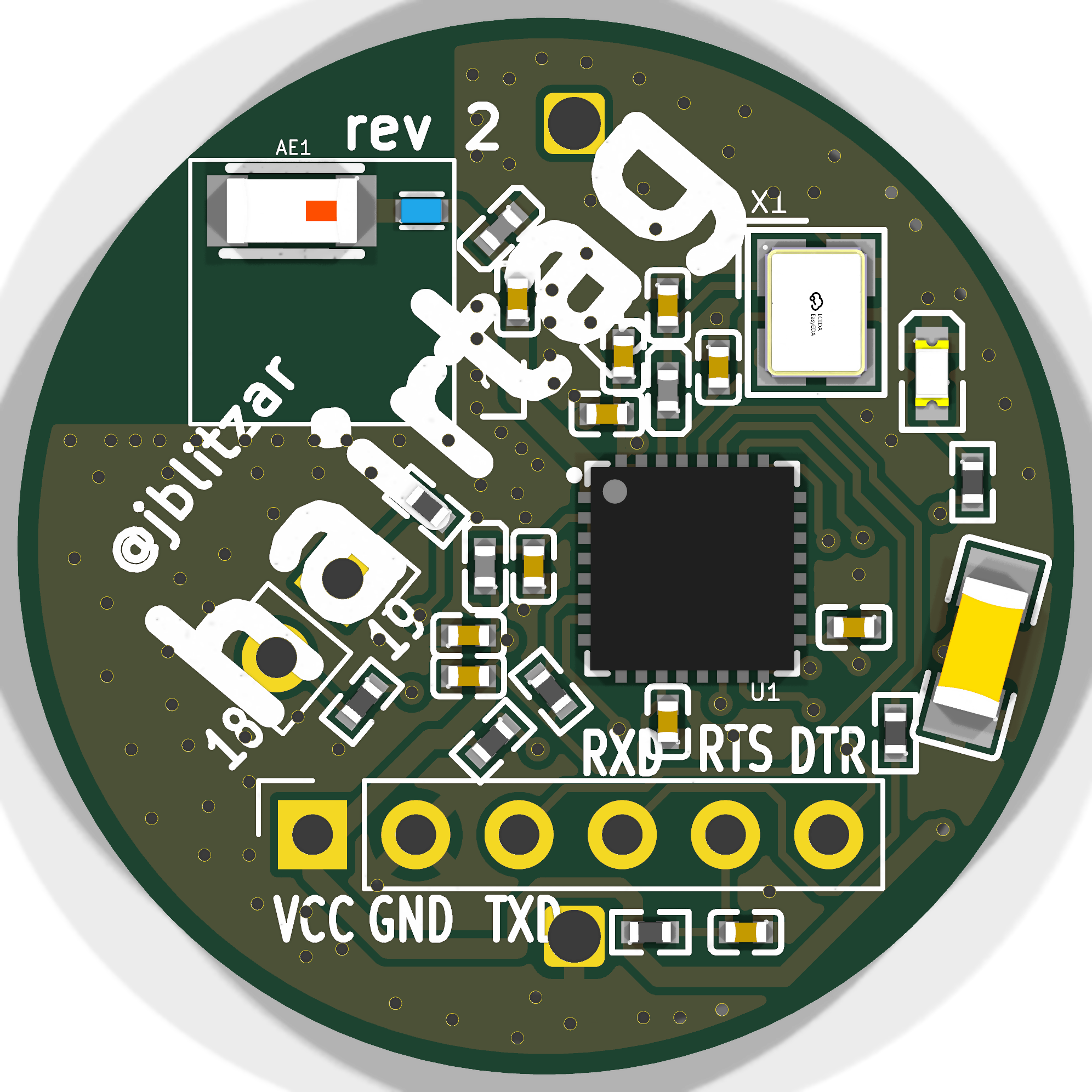
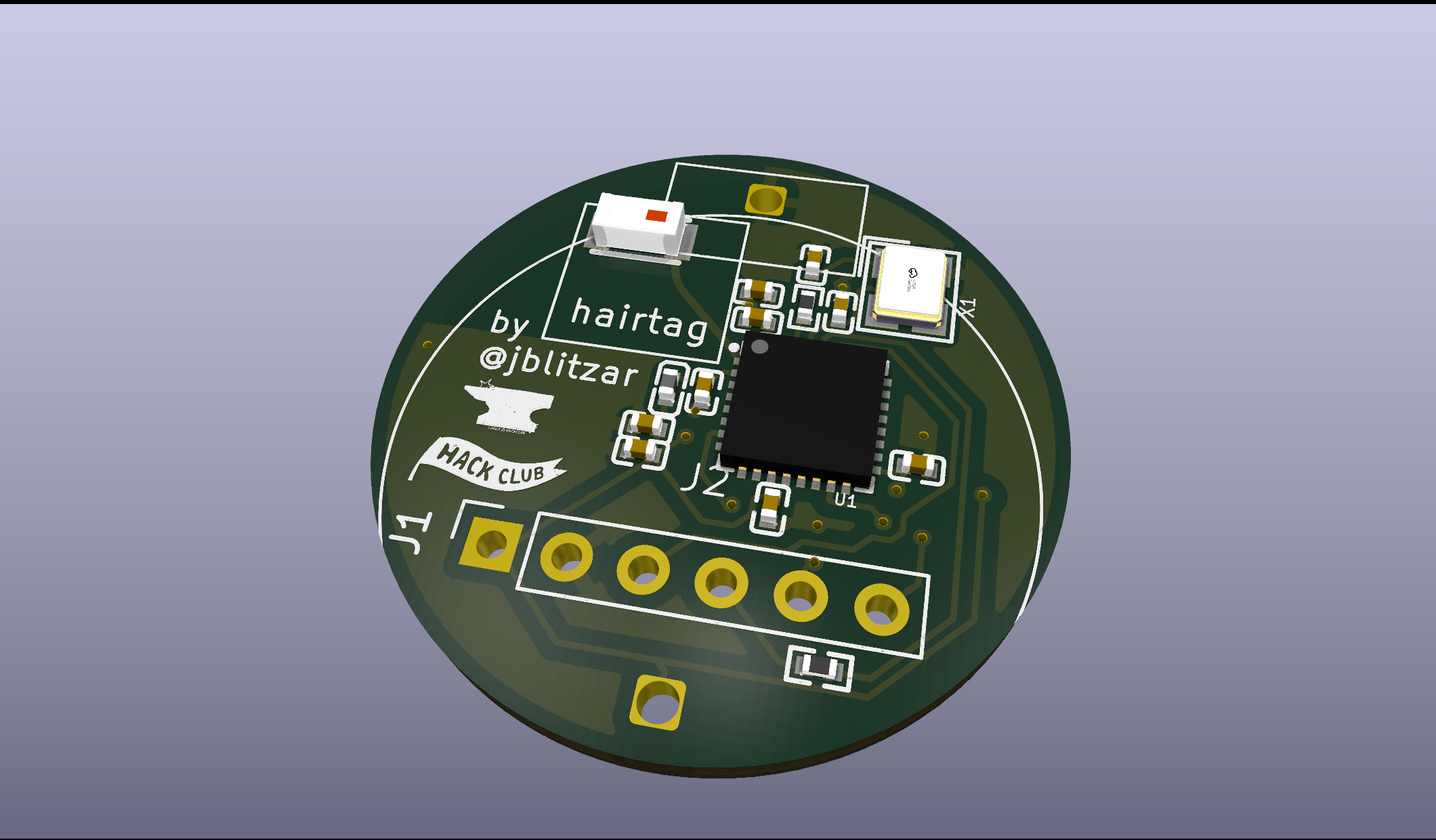
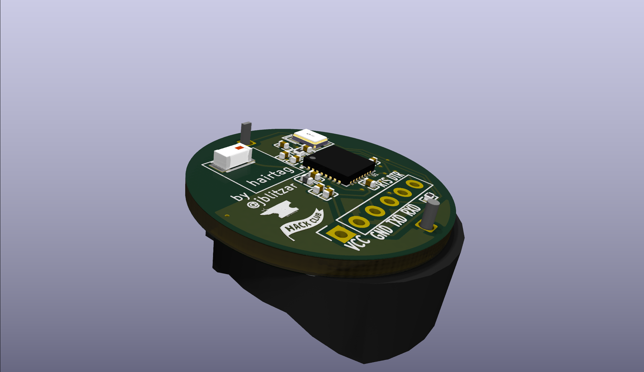
Hairtag is an open-source printed circuit board by JBlitzar, from the JBlitzar/hairtag repository on GitHub, published under the GPL-3.0 licence. It is a 2-layer board with 30 parts on 37 nets, routed with 241 tracks and 120 vias.
It is built around the ESP32-C3FH4, 0402CG150J500NT and 2450AT18A100E, with the MLG1005S2N0BT000, FRC0402F4990TS and XL2EL89CPI-111YLC-40M among its other parts. Its parts include 12 capacitors, 7 resistors, 4 inductors, 2 connectors and 1 IC. It belongs with the ESP32 and RISC-V boards of this library.


homemade airtag that's genuinely pretty good
I thought airtags were pretty cool. A while ago I was scrolling Github and I came across openhaystack (btw Seemoo lab has done all sorts of cool things that I've used before, shoutout to nexmon and opendrop).
Anyways, I figured I could make my own. It's good experience, because you basically get all the components of a devboard, plus power budgeting, and interesting firmware. Plus, I already own 10000 devboards but I own zero airtags so this is a product that I'd actually use and want. A project that has both cool value and educational value gives you so much more motivation than one that only has the latter.

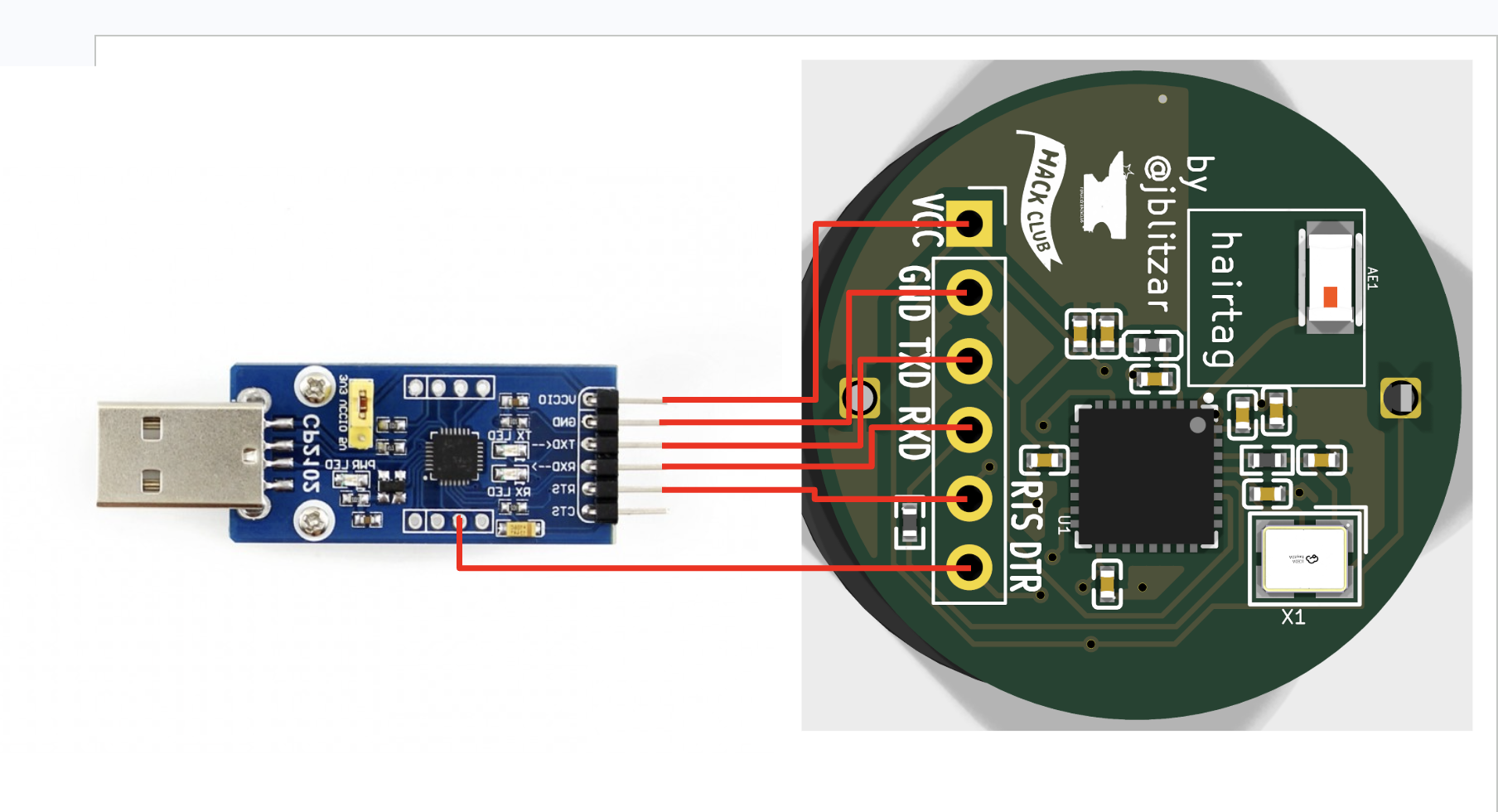
The standard way is a CP2102 USB-UART dongle wired straight to the flashing header (VCC, GND, TXD, RXD, EN, DTR):
Alternatively, if you have an Icepi Zero FPGA, you can use its onboard USB-UART bridge as the flasher. See software/fpga/.
https://github.com/user-attachments/assets/a9827342-8f9d-4dc0-8821-d6cf14613d8d
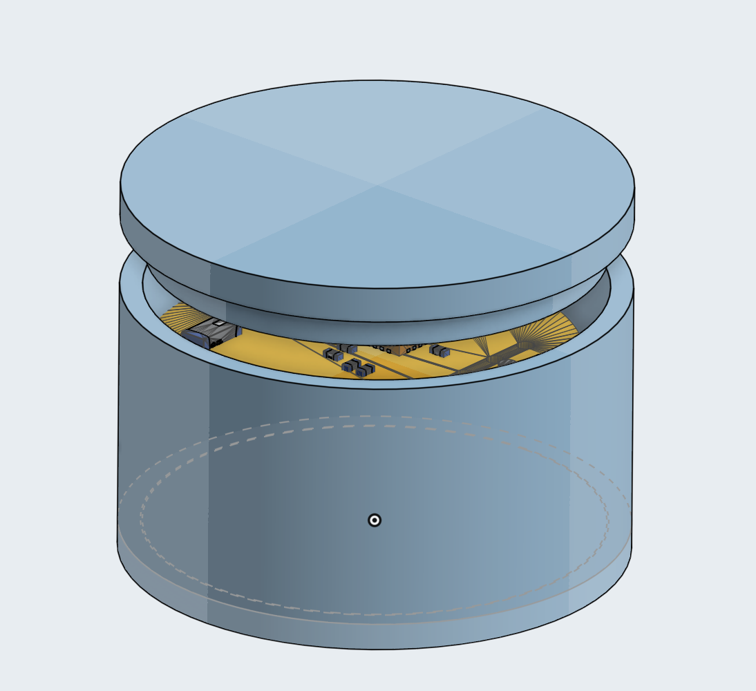
See software/README.md. It's quite involved.
| Item | Link | Cost | Notes | Running Total |
|---|---|---|---|---|
| CP2102 for flashing | http://waveshare.com/cp2102-usb-uart-board-type-a.htm | 4.99 | This one has a specific pinout that's useful, also waveshare's more reputable | 4.99 |
| PCB + PCBA + JLC shipping | N/A | 42.02 | Cost for 2x pcba. I'm willing to pay $4 extra out of pocket to get the 5x PCBA | 47.01 |
| CR2032 batteries | https://www.aliexpress.us/item/3256808176964698.html | 0 | self-sourced, alt amazon link: https://www.amazon.com/Energizer-2032-Battery-CR2032-Lithium/dp/B0042A9UXC?th=1 | 47.01 |
| battery holder | https://www.amazon.com/RuiLing-CR2032-Button-Battery-Holder/dp/B07PNK5D6H | 6.69 | it's actually cheaper than what I could find on aliexpress (at least that had the footprint that I wanted and free shipping) | 53.7 |
| Shipping / taxes | N/A | 11 | TBD, from all the other ones not counting pcba | 64.7 |
| Case (printed) | N/A | 0 | self-sourced, alternatively print legion is also free | 64.7 |
| Qty | Value | Footprint | References |
|---|---|---|---|
| 3 | 0.1uF | lcsc:C0402 | C2, C4, C7 |
| 3 | 10k | lcsc:R0402 | R4, R5, R6 |
| 3 | 1uF | lcsc:C0402 | C1, C5, C8 |
| 2 | 15pf | lcsc:C0402 | C9, C10 |
| 2 | 22 | lcsc:R0402 | R2, R7 |
| 1 | 0402WGF3300TCE | lcsc:R0402 | R3 |
| 1 | 100uF | lcsc:C1206 | C11 |
| 1 | 10nF | lcsc:C0402 | C6 |
| 1 | 10uF | lcsc:C0402 | C3 |
| 1 | 15nH | lcsc:L0402 | L2 |
| 1 | 1pF | easyeda2kicad:C0402 | C12 |
| 1 | 2.7nH | easyeda2kicad:L0402 | L3 |
| 1 | 2450AT18A100E | lcsc:ANT-SMD_L3.2-W1.6 | AE1 |
| 1 | 2nH | lcsc:L0402 | L1 |
| 1 | 3.9nH | easyeda2kicad:IND-SMD_L1.0-W0.5-2 | L4 |
| 1 | 499Ω | lcsc:R0402 | R1 |
| 1 | BAT | cr2032_holder:Untitled | J2 |
| 1 | ESP32-C3FH4 | lcsc:QFN-32_L5.0-W5.0-P0.50-TL-EP3.7 | U1 |
| 1 | FC-1608YXK-585F08 | lcsc:LED0603-RD | LED1 |
| 1 | Flash | Connector_PinSocket_2.54mm:PinSocket_1x06_P2.54mm_Vertical | J1 |
| 1 | USB | Connector_PinSocket_2.54mm:PinSocket_1x02_P2.54mm_Vertical | USB1 |
| 1 | XL2EL89CPI-111YLC-40M | lcsc:CRYSTAL-SMD_4P-L3.2-W2.5-BL | X1 |
quintenluyten2/Pocket_2.66_E-reader_PCB
PCB for 2.13" and 2.66" E-ink displays with ESP32-C3, micro-SD card, battery management, and 3 user buttons

OpenDrone-hw/OpenRX-Gemini
Open-source dual-radio, dual-band ExpressLRS receiver for Gemini and Xrossband.

OpenDrone-hw/OpenRX-Lite
Open-source 2.4 GHz ExpressLRS receiver with an on-board ceramic antenna.

OpenDrone-hw/OpenRX-Mono
Open-source dual-band ExpressLRS receiver with one LR1121 radio and one U.FL antenna.

manhoosbilli1/esp32-dongle-v0-1-ceramic-antenna
Smallest possible ESP32 dongle v0.1 with ceramic antenna - untested (never manufactured)

yasir-shahzad/OpenRX
Open-source ExpressLRS 4.0 receiver family. Part of the OpenDrone ecosystem.

jackw01/scanlight
A better light source for scanning color negative film

theohg/PD240W
PD240W is a complete hardware and firmware project converting USB-C Power Delivery into a programmable 240W (48V 5A) bench power supply, featuring C++ code for Raspberry Pi Pico, custom PCB Gerbers, and a 3D-printable…
30 parts, built around the ESP32-C3FH4, 0402CG150J500NT, 2450AT18A100E and MLG1005S2N0BT000. The full list of its parts is on this page, with links to each part's symbol and footprint where PCBKit's library has them.
From the JBlitzar/hairtag repository on GitHub, at the commit this page was made from: the board is PCB/hairtag/hairtag.kicad_pcb and its schematic PCB/hairtag/hairtag.kicad_sch. PCBKit opens the board in the browser, with nothing to install.
Its repository publishes it under the GPL-3.0 licence: you may reuse it on that licence's terms (keep the author's notice, and for a copyleft licence share your changes alike).