2 layers

 JBlitzar/flsh
flashlight
Flsh is an open-source printed circuit board by JBlitzar, from the JBlitzar/flsh repository on GitHub, published under the GPL-3.0 licence. It is a 2-layer board with 19 parts on 7 nets, routed with 48 tracks and 86 vias.
It is built around the XL6006E1, CL31B105KCHNNNE and MA80V100M10X12, with the KTJ350B476M55BFT00, JER2512F2R220 and SS38 among its other parts. Its parts include 4 capacitors, 1 resistor, 1 IC, 1 diode and 1 inductor.


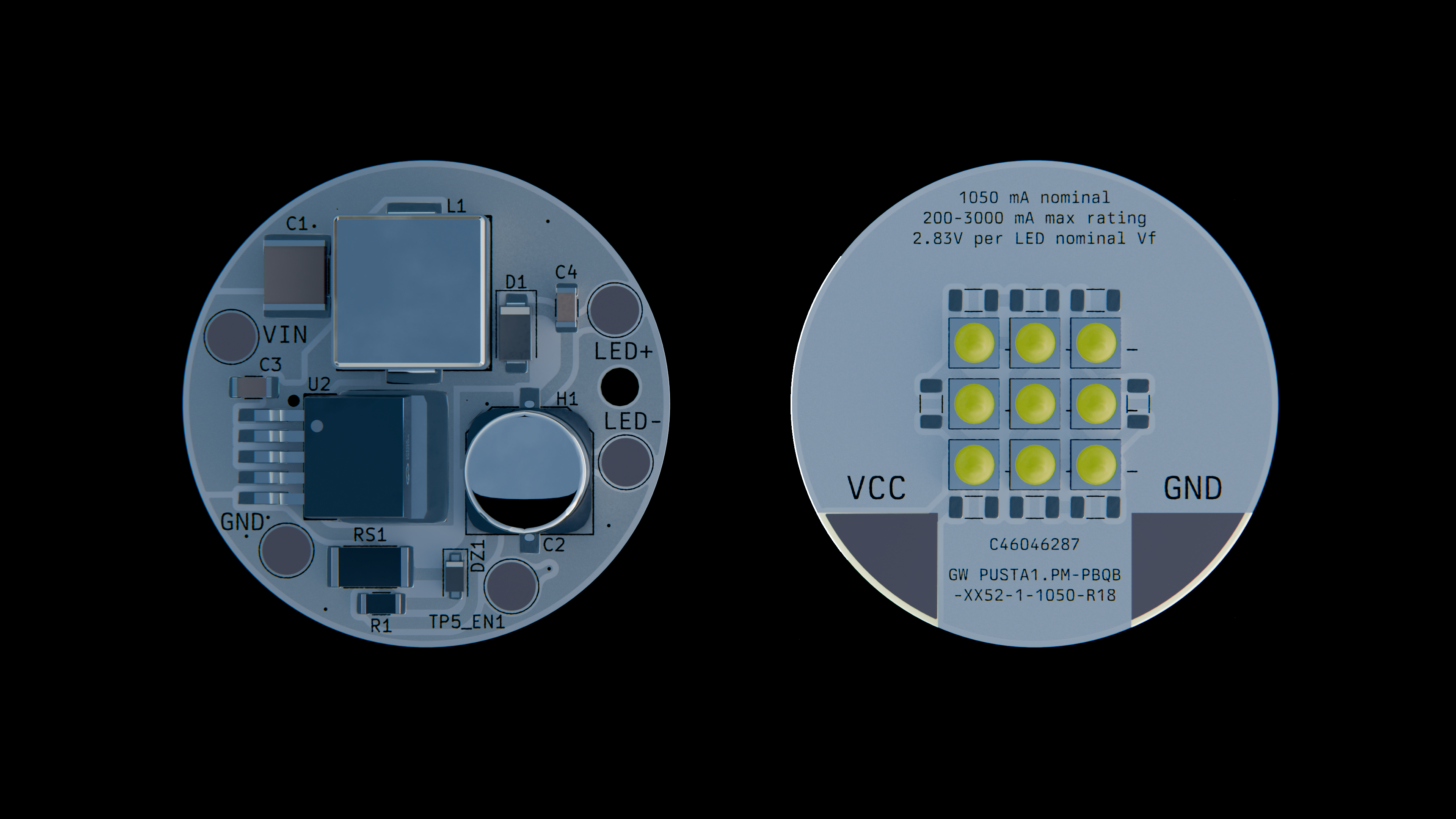
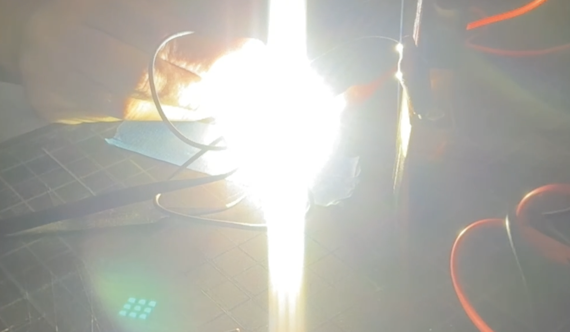
A flashlight with the brightness of 83 iphones.
Some features:
I made this because I thought it would be pretty cool. Also I got to think about designing power circuitry. I looked at a lot of different ICs before settling on the XL6006. In the end, TI and Analog both were beaten out by Shanghai Xinlong Semiconductor Technology Co., Ltd, so there you go! While the XL6006 gets a bad rap on cheap aliexpress boost boards, the chip itself will work fine if you have a good inductor etc. And it only requires like five passives to work! I evaluated a lot of different designs, see planning.
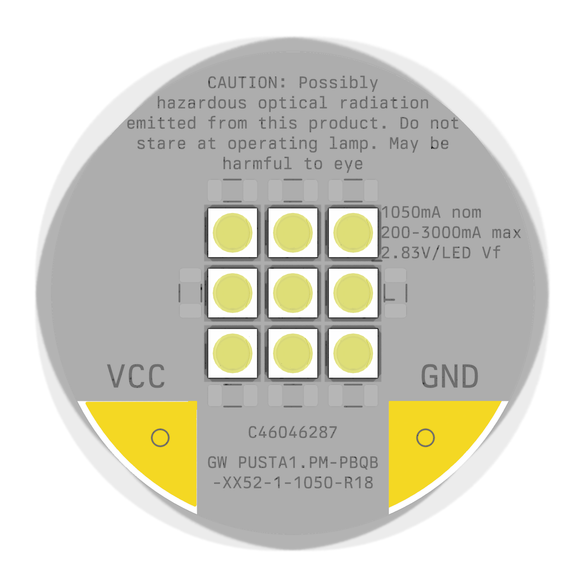
In terms of the LEDs, I pretty much went on to LCSC and clicked "sort high to low" on lumens. But really, I thought this was more reasonable than most CoB solutions.
You might be wondering why they are in series. This is to prevent thermal runaway, where one LED uses slightly more current, which causes it to get hotter, which causes it to hog current slightly more, etc in a positive feedback loop. You can use ballast resistors. I just wired them in series and accepted the steep boost ratio.
PWM dimming? hahaha you can source and solder a different sense resistor to get a different brightness.
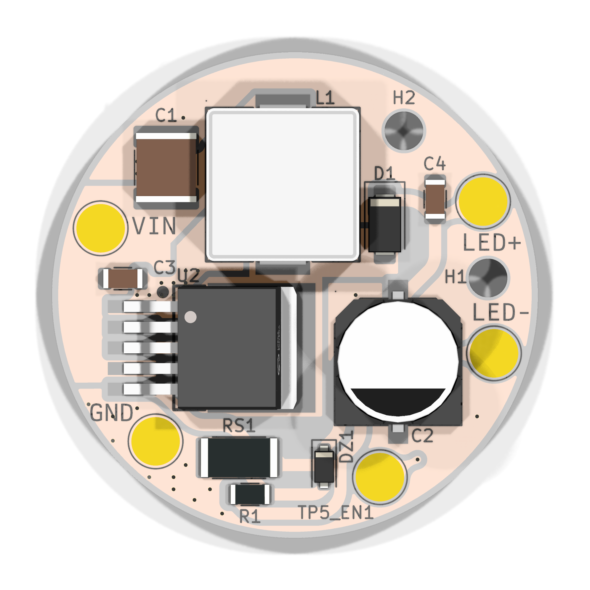
2x21700 to VIN / GND on the boost board, then LED+ / LED- on the boost board to VCC / GND on the emitter board.
As you can tell, this is, for the moment, mostly the bones of a flashlight (ie the PCBs) rather than an actual assembly.
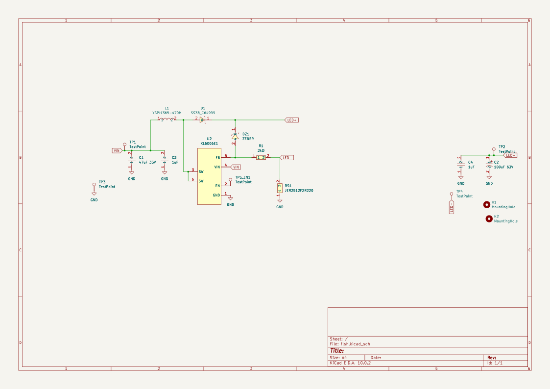
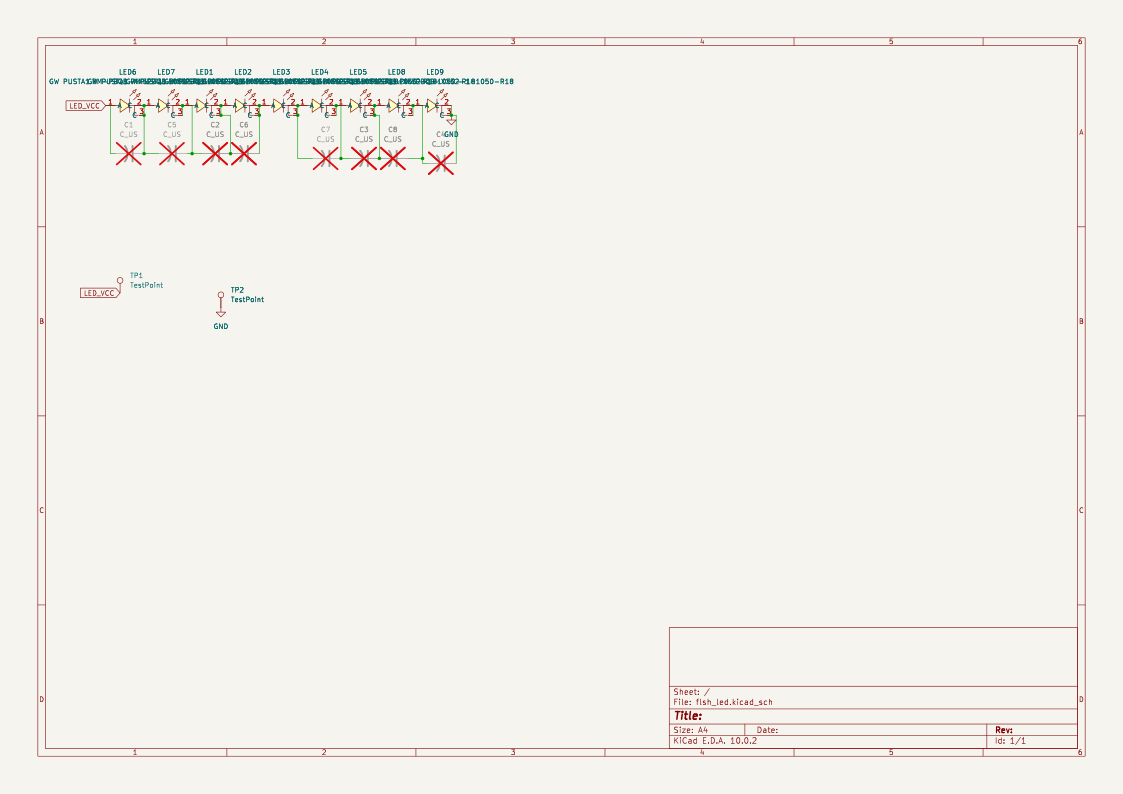
View on KiCanvas | View iBOM (or open PCB/flsh/bom/ibom.html locally)
 |  |
 |  |
This is a ballpark, YMMV based on sourcing, promotions, discounts
| Item | Link | Extended Cost | Notes |
|---|---|---|---|
| 10x LEDs (MOQ) | https://www.lcsc.com/product-detail/C46046287.html | 17.15 | |
| LED PCB | N/A | 2.44 | |
| Boost components | N/A | 18 | See fabrication BOM in README for C-numbers |
| LCSC shipping | N/A | 8 | |
| JLC shipping | N/A | 3.3 | |
| Total | 48.89 |
| Designator | Footprint | Quantity | Value | LCSC Part # |
|---|---|---|---|---|
| C1 | C_2220_5750Metric | 1 | 47uF 35V | C27840590 |
| C2 | CAP-SMD_BD10.0-L10.3-W10.3-FD | 1 | 100uF 63V | C53120969 |
| C3, C4 | C_1206_3216Metric | 2 | 1uF | C13832 |
| D1 | D_SMA | 1 | SS38 | C64999 |
| DZ1 | D_SOD-123F | 1 | ZENER (BZT52C39, 39V) | C49023525 |
| L1 | IND-SMD_L13.8-W12.6_H6.5 | 1 | YSPI1365-470M (47uH) | C497913 |
| R1 | R_1206_3216Metric | 1 | 2k | C133543 |
| RS1 | R_2512_6332Metric | 1 | JER2512F2R220 (0.22R) | C49164922 |
| U2 | TO-263-5_L10.2-W9.9-P1.70-LS14.4-TL | 1 | XL6006E1 | C73346 |
| Designator | Footprint | Quantity | Value | LCSC Part # |
|---|---|---|---|---|
| LED1, LED2, LED3, LED4, LED5, LED6, LED7, LED8, LED9 | LED-SMD_3P-L3.7-W3.7_GW-PUSTA1.PM-NAPD-XX510-1-1050-R18 | 9 | GW PUSTA1.PM-PBQB-XX52-1-1050-R18 | C46046287 |
| Qty | Value | Footprint | References |
|---|---|---|---|
| 5 | TestPoint | TestPoint:TestPoint_Pad_D4.0mm | TP1, TP2, TP3, TP4, TP5_EN1 |
| 3 | MountingHole | MountingHole:MountingHole_3.2mm_M3 | H1, H2, H3 |
| 2 | 1uF | Capacitor_SMD:C_1206_3216Metric | C3, C4 |
| 1 | 100uF 63V | easyeda2kicad:CAP-SMD_BD10.0-L10.3-W10.3-FD | C2 |
| 1 | 2kΩ | Resistor_SMD:R_1206_3216Metric | R1 |
| 1 | 47uF 35V | Capacitor_SMD:C_2220_5750Metric | C1 |
| 1 | JER2512F2R220 | Resistor_SMD:R_2512_6332Metric | RS1 |
| 1 | Kobee Studio | kobee-studio-6ADE59CA | kobee-studio-6ADE59CA |
| 1 | SS38_C64999 | Diode_SMD:D_SMA | D1 |
| 1 | XL6006E1 | easyeda2kicad:TO-263-5_L10.2-W9.9-P1.70-LS14.4-TL | U2 |
| 1 | YSPI1365-470M | easyeda2kicad:IND-SMD_L13.8-W12.6_H6.5 | L1 |
| 1 | ZENER | Diode_SMD:D_SOD-123F | DZ1 |

yukselturkomer/50w-buck-converter-stm32
Bu proje, STM32 mikrodenetleyici kullanılarak geliştirilmiş 50W kapasiteli bir Buck (Düşürücü) Konvertör sistemini ve bu sistemin kontrolünü sağlayan Nextion HMI (İnsan-Makine Arayüzü) tasarımını içermektedir.

MycroftAI/hardware-mycroft-mark-II
Mycroft's Mark II Rpi mechanical, electrical and industrial designs


Ibmkakinwande/5v-linear-regulator
An introduction to hardware design and PCB layout featuring a classic 5V L7805 voltage regulator circuit.

KrystianRuszczak/BioSense
The hardware design files in this directory are licensed under CERN-OHL-P-2.0. See LICENSE.

HelloAlex4/Maturitaetsarbeit-Design-and-Development-of-a-Portable-Stereoscopic-Wigglegram-Camera
Documentation of the merged wigglegram camera
19 parts, built around the XL6006E1, CL31B105KCHNNNE, MA80V100M10X12 and KTJ350B476M55BFT00. The full list of its parts is on this page, with links to each part's symbol and footprint where PCBKit's library has them.
From the JBlitzar/flsh repository on GitHub, at the commit this page was made from: the board is PCB/flsh/flsh.kicad_pcb and its schematic PCB/flsh/flsh.kicad_sch. PCBKit opens the board in the browser, with nothing to install.
Its repository publishes it under the GPL-3.0 licence: you may reuse it on that licence's terms (keep the author's notice, and for a copyleft licence share your changes alike).
