

4 layers46.8 × 34.8 mm
SmartWatch V4
Bellafaire/ESP32-Smart-Watch
An open source smartwatch based on the ESP32 compatible with the Arduino IDE.
74 parts258MIT

 jblb/micro_pro_plc
Arduino Micro pro PLC board
Pro micro plc is an open-source printed circuit board by jblb, from the jblb/micro_pro_plc repository on GitHub. It is a 2-layer board of 75 × 40.5 mm with 42 parts on 42 nets, routed with 186 tracks and 32 vias.
It is built around the MAX485ED and 2N7002K. Its parts include 15 resistors, 7 connectors, 6 ICs, 4 diodes and 4 transistors. It belongs with the AVR (ATmega, ATtiny) boards of this library.
work in progress...
Micro pro PLC is a small Programable Logic Controlor board based on Arduino micro pro (ATmega32U4 microcontroler). It is designed for small systems with 4 digital inputs, 4 digital outputs, 2 analog inputs and a Modbus/RS485 access. It is designed to fit on easy available 4 way relay board
I first designed it for use with open_PLC but it can be use with Arduino IDE or any other way you want to devellop the software you put on the controler
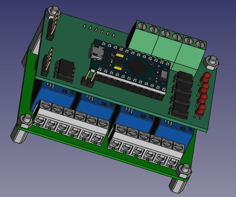
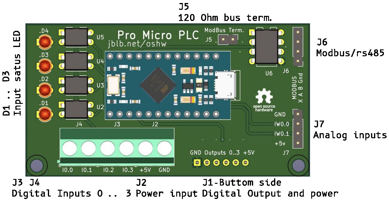
| Board pin | Arduino pin |
|---|---|
| I0.0 | D2 |
| I0.1 | D3 |
| I0.2 | D4 |
| I0.3 | D5 |
| Output0 | D7 |
| Output1 | D8 |
| Output2 | D14 |
| Output3 | D15 |
| IW0.0 | A0 |
| IW0.1 | A1 |
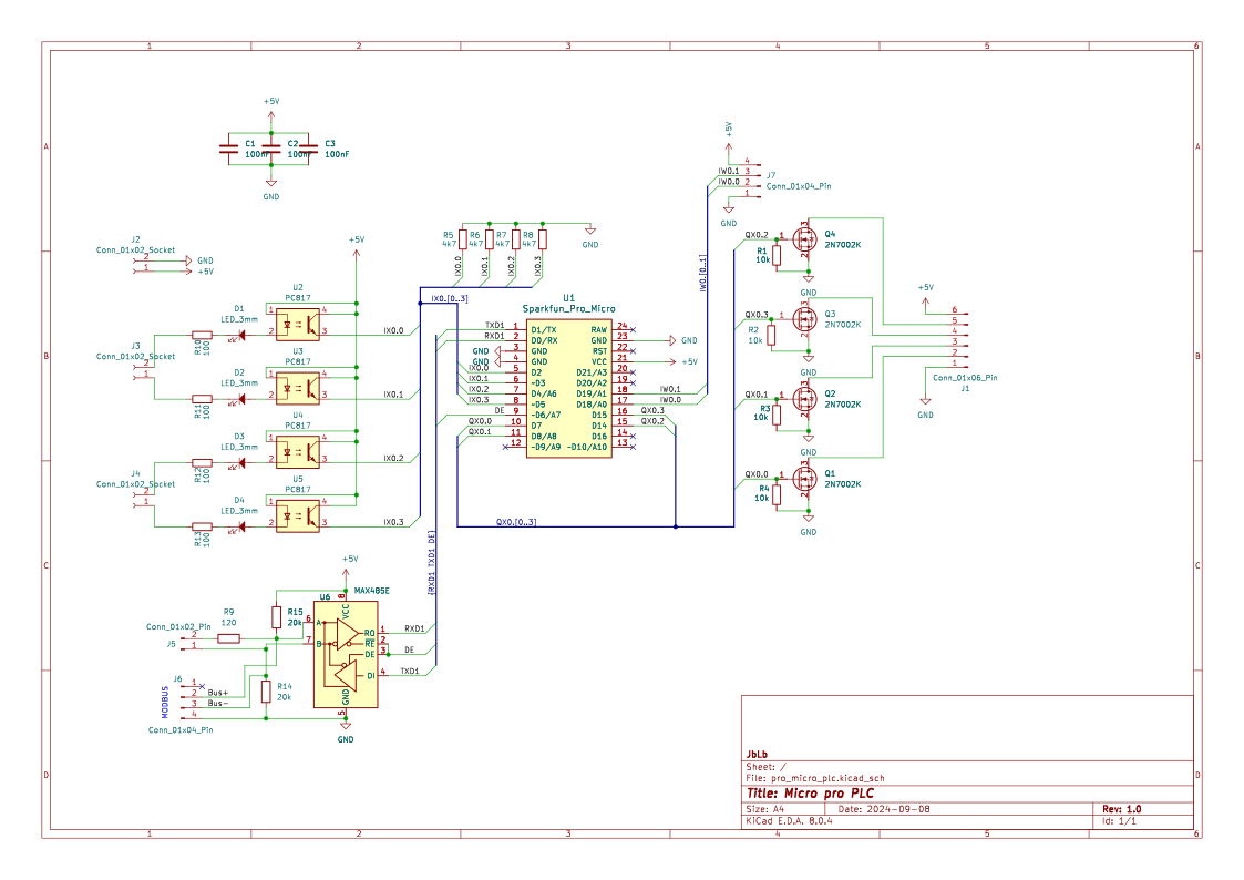
PDF version available here
| Reference | Value | Footprint |
|---|---|---|
| C1,C2,C3 | 100nF | SMD 0805 |
| D1,D2,D3,D4 | LED_3mm | |
| J1 | 01x06_Pin | PinSocket_2.54mm |
| J2,J3,J4 | TerminalBlock_Phoenix_MKDS 5.00mm | |
| J5 | 01x02_Pin | PinHeader_2.54mm |
| J6,J7 | 01x04_Pin | PinHeader_2.54mm or JST HX |
| Q1,Q2,Q3,Q4 | 2N7002K | SOT-23 |
| R1,R2,R3,R4 | 10k | SMD 0805 |
| R5,R6,R7,R8 | 4k7 | SMD 0805 |
| R9 | 120 | SMD 0805 |
| R10,R11,R12,R13 | 100 | SMD 0805 |
| R14,R15 | 20k | SMD 0805 |
| U1 | Sparkfun_Pro_Micro or Clone | |
| U2,U3,U4,U5 | PC817 | DIP4 |
| U6 | MAX485E | DIP8 |
also available here
| Qty | Value | Footprint | References |
|---|---|---|---|
| 4 | 100 | Resistor_SMD:R_0805_2012Metric_Pad1.20x1.40mm_HandSolder | R10, R11, R12, R13 |
| 4 | 10k | Resistor_SMD:R_0805_2012Metric_Pad1.20x1.40mm_HandSolder | R1, R2, R3, R4 |
| 4 | 2N7002K | Package_TO_SOT_SMD:SOT-23_Handsoldering | Q1, Q2, Q3, Q4 |
| 4 | 4k7 | Resistor_SMD:R_0805_2012Metric_Pad1.20x1.40mm_HandSolder | R5, R6, R7, R8 |
| 4 | LED_3mm | LED_THT:LED_D3.0mm | D1, D2, D3, D4 |
| 4 | PC817 | Package_DIP:DIP-4_W7.62mm | U2, U3, U4, U5 |
| 3 | 100nF | Capacitor_SMD:C_0805_2012Metric_Pad1.18x1.45mm_HandSolder | C1, C2, C3 |
| 3 | Conn_01x02_Socket | TerminalBlock_Phoenix:TerminalBlock_Phoenix_MKDS-1,5-2_1x02_P5.00mm_Horizontal | J2, J3, J4 |
| 2 | 20k | Resistor_SMD:R_0805_2012Metric_Pad1.20x1.40mm_HandSolder | R14, R15 |
| 2 | Conn_01x04_Pin | Connector_PinHeader_2.54mm:PinHeader_1x04_P2.54mm_Vertical | J6, J7 |
| 1 | 120 | Resistor_SMD:R_0805_2012Metric_Pad1.20x1.40mm_HandSolder | R9 |
| 1 | Conn_01x02_Pin | Connector_PinHeader_2.54mm:PinHeader_1x02_P2.54mm_Vertical | J5 |
| 1 | Conn_01x06_Pin | Connector_PinSocket_2.54mm:PinSocket_1x06_P2.54mm_Vertical | J1 |
| 1 | MAX485E | Package_DIP:DIP-8_W7.62mm | U6 |
| 1 | Sparkfun_Pro_Micro | Arduino:Sparkfun_Pro_Micro | U1 |
The 39 most common of 42 parts.
It measures 75 × 40.5 mm and has 2 copper layers, 1.6 mm thick.
42 parts, built around the MAX485ED and 2N7002K. The full list of its parts is on this page, with links to each part's symbol and footprint where PCBKit's library has them.
From the jblb/micro_pro_plc repository on GitHub, at the commit this page was made from: the board is pro_micro_plc.kicad_pcb and its schematic pro_micro_plc.kicad_sch. PCBKit opens the board in the browser, with nothing to install.
Its repository states no licence, so its author keeps all rights: ask jblb before reusing the design.
Bellafaire/ESP32-Smart-Watch
An open source smartwatch based on the ESP32 compatible with the Arduino IDE.


AaronC81/delta-pico
Powerful scientific calculator based on the Raspberry Pi Pico

avenhaus/SO-ARM100-Encoders
It explores to use much cheaper magnetic encoders for the Leader Arm instead of the regular servos. These dummy servos are also much easier to move manually, as there is no gear train that needs to back drive the servo…


OpenLogicEFI/Hardware
Hardware is based off an open source project called Speeduino by Josh Stewart.