

2 layers130.8 × 147.6 mm
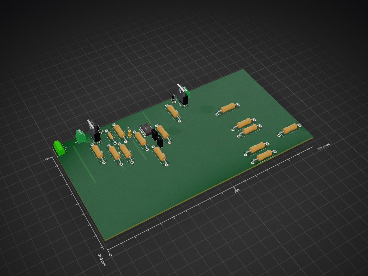
 jbeyers/pendulum_wave1
Design files for a perpetual pendulum wave machine.
Dual driver is an open-source printed circuit board by jbeyers, from the jbeyers/pendulum_wave repository on GitHub. It is a 2-layer board with 26 parts on 17 nets, routed with 38 tracks and 14 vias.
It is built around the LM358 and IRF540N. Its parts include 16 resistors, 5 connectors, 2 diodes, 2 transistors and 1 IC.
A pendulum wave is formed by a row of pendulums, each with a slightly different period. When started at the same time, they swing in a row, but quickly turn into a sinewavey snake shape, go through a whole set of interesting patterns and then end up in a straight row again.
The only ones I've seen are started and tuned manually.
Using steel bearing balls with magnets for the pendulums, and giving them a bit of a kick every now and again with a wire solenoid coil, the pendulums can be made to swing continuously. However, they would go out of tune after a few cycles.
The length of the pendulums are adjustable, so I can get them pretty close.
Getting the pendulums to vary their period is the tricky bit. This is slightly difficult to explain, but since the pendulums are built with fishing line, I can add a secondary pivot point below the first one, which will only kick in once the swing is larger than a certain angle. This causes the overall period to shorten if the angle increases.
Each coil has a sensing circuit to detect the pendulum swinging overhead. The coil is slightly offset to one side so that it can determine the direction of the swing from the slight difference in sensing time between the left and right swings.
Each coil is pulsed under PID control, so they sync up no matter what the initial positions are.
This repository contains various files. In general, licensing is CC-BY-SA-4.0 for the designs and MIT for the software. Let me know if you need clarification.
| Qty | Value | Footprint | References |
|---|---|---|---|
| 9 | 1k | Resistors_THT:R_Axial_DIN0516_L15.5mm_D5.0mm_P20.32mm_Horizontal | R2, R3, R4, R7, R11, R13, R14, R15, R16 |
| 2 | 10k | Resistors_THT:R_Axial_DIN0516_L15.5mm_D5.0mm_P20.32mm_Horizontal | R8, R9 |
| 2 | 2k7 | Resistors_THT:R_Axial_DIN0516_L15.5mm_D5.0mm_P20.32mm_Horizontal | R6, R10 |
| 2 | Conn_01x02_Female | Socket_Strips:Socket_Strip_Straight_1x02_Pitch2.54mm | J2, J3 |
| 2 | D | Diodes_THT:D_DO-41_SOD81_P2.54mm_Vertical_AnodeUp | D1, D2 |
| 2 | IRF540N | TO_SOT_Packages_THT:TO-220-3_Vertical | Q1, Q2 |
| 2 | Screw_Terminal_01x02 | TerminalBlocks_Phoenix:TerminalBlock_Phoenix_MPT-2.54mm_2pol | J1, J4 |
| 1 | 100k | Resistors_THT:R_Axial_DIN0204_L3.6mm_D1.6mm_P2.54mm_Vertical | R5 |
| 1 | 100k | Resistors_THT:R_Axial_DIN0516_L15.5mm_D5.0mm_P20.32mm_Horizontal | R12 |
| 1 | 1k | Resistors_THT:R_Axial_DIN0414_L11.9mm_D4.5mm_P15.24mm_Horizontal | R1 |
| 1 | LM358 | Housings_DIP:DIP-8_W7.62mm | U1 |
| 1 | Screw_Terminal_01x02 | Connectors_Terminal_Blocks:TerminalBlock_bornier-2_P5.08mm | J5 |
26 parts, built around the LM358 and IRF540N. The full list of its parts is on this page, with links to each part's symbol and footprint where PCBKit's library has them.
From the jbeyers/pendulum_wave repository on GitHub, at the commit this page was made from: the board is electronics/dual_driver.kicad_pcb. PCBKit opens the board in the browser, with nothing to install.
Its repository states no licence, so its author keeps all rights: ask jbeyers before reusing the design.


dario0603/electronic_load
Un progetto open-source per la progettazione e simulazione di un Carico Elettronico Bipolare (Electronic Load), ideato per il test e la caratterizzazione di alimentatori, batterie e circuiti di potenza.


kwiecinski/BMS-and-offgrid-photovoltaic-management-system
Project contains BMS for lead-acid batteries and ESP-based board used to pull information from EASUN offgrid inverter, energy meters and sensors.

ArgonautGit/kicad-projects
Just some Kicad projects I've worked on over the years. Most are unfinished or don't work well.


profdc9/DRSSTC-PCB-Pack
A pack of PCBs for a dual resonant solid state tesla coil setup. Pretty much everything you need.