
2 layers123.3 × 95 mm

 JayesonLS/ISA-Cards21
ISA Card Designs for Use in Vintage PCs
XTA Interface is an open-source printed circuit board by JayesonLS, from the JayesonLS/ISA-Cards repository on GitHub. It is a 2-layer board of 101.9 × 99.9 mm with 19 parts on 88 nets, routed with 1,165 tracks and 207 vias.
It is built around the 74HCT245. Its parts include 5 capacitors, 5 connectors, 4 ICs and 1 resistor. It belongs with the retro computing and games and interfaces and adapters boards of this library.
ISA card designs for use in Vintage PCs.
Status: Fit tested and appears correct.
Description: A template from which to build ISA cards. The board dimensions around the edge connector are from an early IBM PC Technical Reference Manual (5150 or 5160). The rear bracket positioning has been measured from an original IBM floppy controller taken from an IBM 5150. This board was an excellent fit when test-fitted in an early Tandy 1000 (25-1000).
The mounting for the CF adapter has also been comfirmed in the same Tandy 1000. It too was a excellent fit.
There may be some variation in fit due to various tolerances. The fit does not seem to be particularly important - a wide variation in fit has been found across various commercial ISA cards.
Status: Untested.
Description: A template from which to design cards and/or back plates for the Tandy 1000 EX/HX computers. Includes approximate board outlines as measured from Tandy's memory/DMA board, Tandy's serial board and Rob Krinecki's 3 in 1 board. Includes various notes about safe areas, potential places to extend the board dimensions, etc.
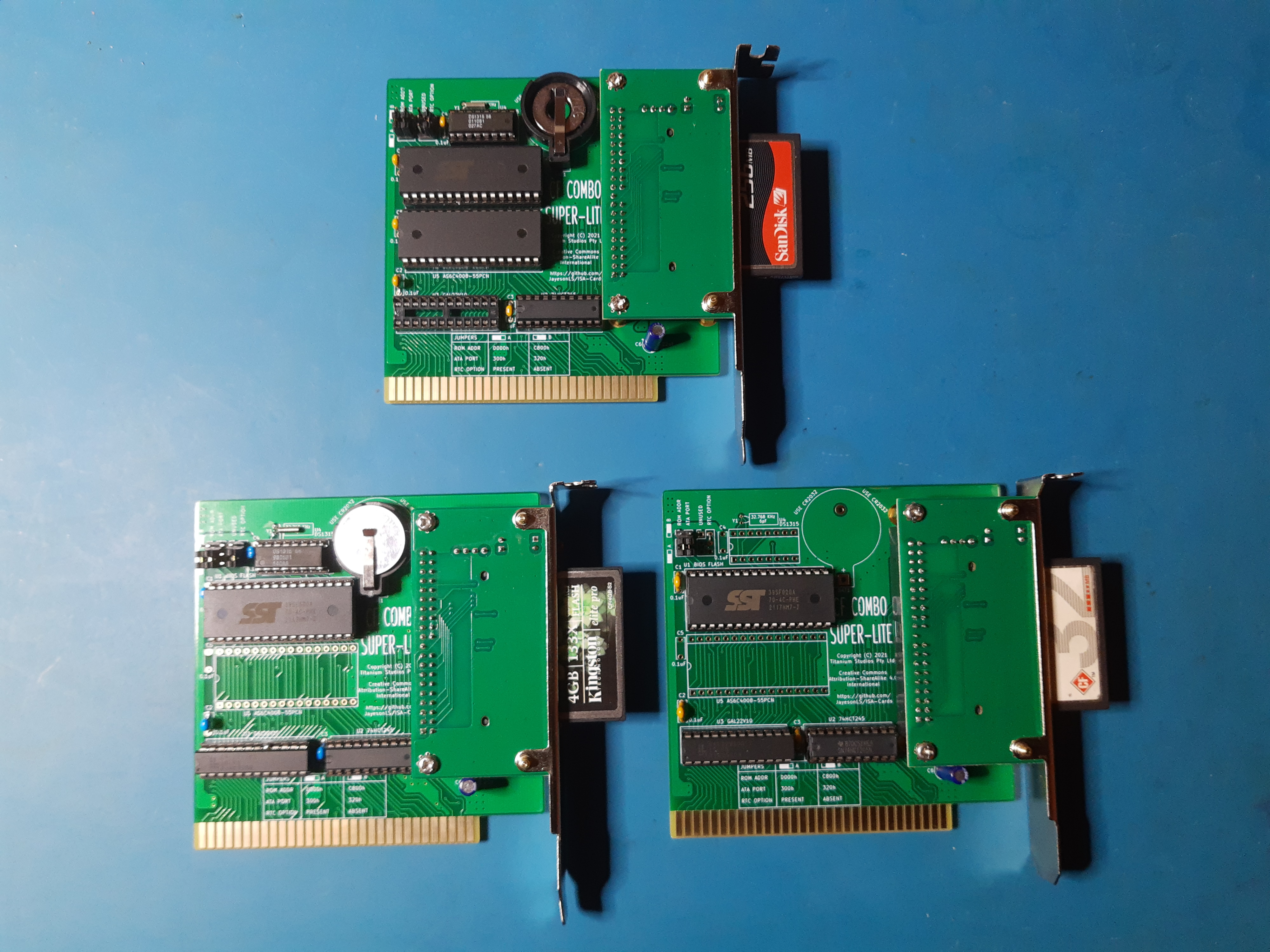
Status: Design built and tested in all configurations. There is a currently an error which may cause issues when other devices are performing DMA transfers. Recommend only the Tandy 1000 configuration of this card which has no DMA present.
Description: An 8 bit ISA card with fully-contained compact flash card and XT-IDE BIOS. This simplified design uses only 3 ICs for the CF/BIOS functionality. It makes use of a commonly availalbe, inexpensive compact flash adapter with integrated mounting bracket.
The board optionally supports the following features:
Status: Built and fully tested. The Rear bracket is located too high and needs to be corrected. No other issues found.
Description: Adds a single 9 pin serial port to a vintage PC. Created with early Tandy 1000's in mind which have no COM ports from the factory.
Decoding is handled by a 74xx688. Alternatively, a JED file is provided for programming the needed decode functionality into a GAL16V8/ATF16V8.
Configuration: Before installing, configure the port selection jumpers to a COM port not yet present in the system. Details are located on the board by the port jumpers. Configure the IRQ jumper to an approriate selection. For no IRQ, remove the IRQ jumper. Suggested IRQ settings are located on the board by the IRQ jumper.
Status: Untested. Vertical positions of serial connectors are only approximate (waiting on a bracket to arrive for reference).
Description: Adds two 9 pin serial ports to a vintage PC. Created with early Tandy 1000's in mind which have no COM ports from the factory.
Configuration: Before installing, configure the port selection jumpers to COM ports not yet present in the system. Details are located on the board by the port jumpers. Configure the IRQ jumpers to an approriate selection. For no IRQ, remove the IRQ jumper. Suggested IRQ settings are located on the board by the IRQ jumpers.
Status: Still in design.
Description: Multiple upgrades for the Tandy 1000 EX/HX in a single board. It adds the following:
Functionality is very similar to Rob Krinecki's 3 in 1/4 in 1 boards, with the following differences:
Status: Tested and works well.
Description: Raises an 8 bit ISA card up out of a desktop case. Makes it easier to probe ISA cards during development/testing. Can optionally fuse the ISA power rails. Low-ohm resistors can be fitted to the power rails to assist with current measurement. ISA pins are marked for easy identification.
Not intended for permanent installation.
The bracket is from a Compact Flash to IDE adapter intended for installation into PCI slots. It must be raised off the board using standoffs totalling 14.6mm high.
Status: Untested.
Description: Allows connection of a Tandy 1000 EX/HX Plus board in a standard ISA slot. Intended for use on an ISA riser board for development/testing.
Not intended for permanent installation.
1 Construction requires programming of one or more GAL16V8/ATF16V8 and/or GAL22V10/ATF22V10 simple programmable logic devices. JED file provided. A TL866 or similar programmer can program most of these devices.
2 Construction requires programming of the required BIOS image into the flash ROM. Most common programmers, such as the TL866, can be used for this.
| Qty | Value | Footprint | References |
|---|---|---|---|
| 4 | 0.1uF | Capacitor_SMD:C_1206_3216Metric | C1, C2, C3, C4 |
| 2 | MountingHole_Pad | MountingHole:MountingHole_3.5mm_Pad | H2, H4 |
| 1 | 22-44uF, 25-35v | Capacitor_Tantalum_SMD:CP_EIA-3528-15_AVX-H | C5 |
| 1 | 220R | Resistor_SMD:R_1206_3216Metric | R1 |
| 1 | 74HCT245 | Package_DIP:DIP-20_W7.62mm_Socket | U2 |
| 1 | ATF/GAL16V8-15 "LEFT" | Package_DIP:DIP-20_W7.62mm_Socket | U3 |
| 1 | ATF/GAL16V8-15 "RIGHT" | Package_DIP:DIP-20_W7.62mm_Socket | U4 |
| 1 | Addresses | Connector_PinHeader_2.54mm:PinHeader_2x03_P2.54mm_Vertical | JP2 |
| 1 | BIOS FLASH | Package_DIP:DIP-32_W15.24mm_Socket | U1 |
| 1 | Bus_ISA_8bit | 00Custom:BUS_XT | J3 |
| 1 | DRIVE 0 | Connector_PinHeader_2.54mm:PinHeader_2x20_P2.54mm_Vertical | CN1 |
| 1 | DRIVE 1 | Connector_PinHeader_2.54mm:PinHeader_2x20_P2.54mm_Vertical | CN2 |
| 1 | Drive Power | Connector_PinHeader_2.54mm:PinHeader_1x06_P2.54mm_Horizontal | CN4 |
| 1 | LEDs | Connector_PinHeader_2.54mm:PinHeader_2x03_P2.54mm_Vertical | CN3 |
| 1 | Options | Connector_PinHeader_2.54mm:PinHeader_2x03_P2.54mm_Vertical | JP1 |
It measures 101.9 × 99.9 mm and has 2 copper layers, 1.6 mm thick.
19 parts, built around the 74HCT245. The full list of its parts is on this page, with links to each part's symbol and footprint where PCBKit's library has them.
From the JayesonLS/ISA-Cards repository on GitHub, at the commit this page was made from: the board is XTA-Interface/XTA-Interface.kicad_pcb. PCBKit opens the board in the browser, with nothing to install.
Its repository states no licence, so its author keeps all rights: ask JayesonLS before reusing the design.


schlae/snark-barker-mca
A Sound Blaster compatible sound card for Micro Channel bus computers

artemisamsx/artemisa
Schematics, PCB designs and HDL simulations to build a 8-bits MSX computer

mecparts/PicoWiFiModem
A Pico W based RS232 <-> WiFi modem with Hayes AT style commands and LED indicators