
2 layers30 × 55 mm

 jasperhax0r/Kaypro10Video
Kaypro video capture and output to HDMI
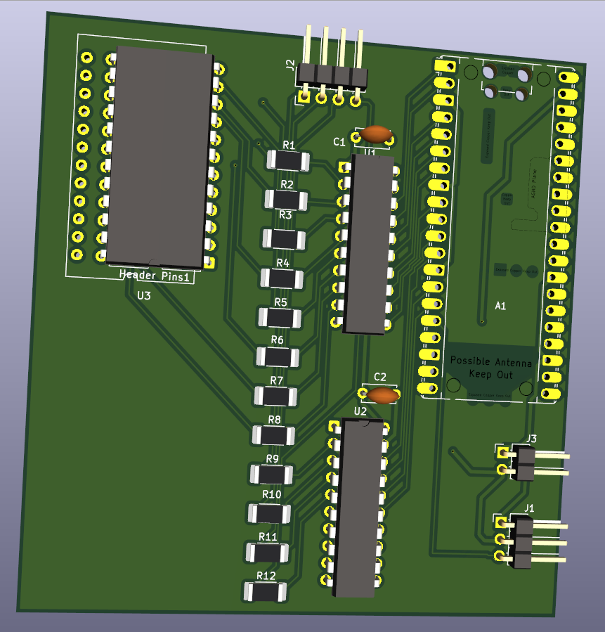
Kaypro10Video is an open-source printed circuit board by jasperhax0r, from the jasperhax0r/Kaypro10Video repository on GitHub, published under the MIT licence. It is a 2-layer board of 80 × 85 mm with 22 parts on 77 nets, routed with 307 tracks and 6 vias.
It is built around the SN74LVC245AN. Its parts include 12 resistors, 3 ICs, 3 connectors and 2 capacitors. It belongs with the interfaces and adapters boards and the RP2040 boards of this library.
A hardware and firmware project that taps the character ROM of a Kaypro 10 CP/M computer and outputs a live HDMI display via a Raspberry Pi Zero 2W running Circle bare metal. No modifications are made to the Kaypro's original circuitry.
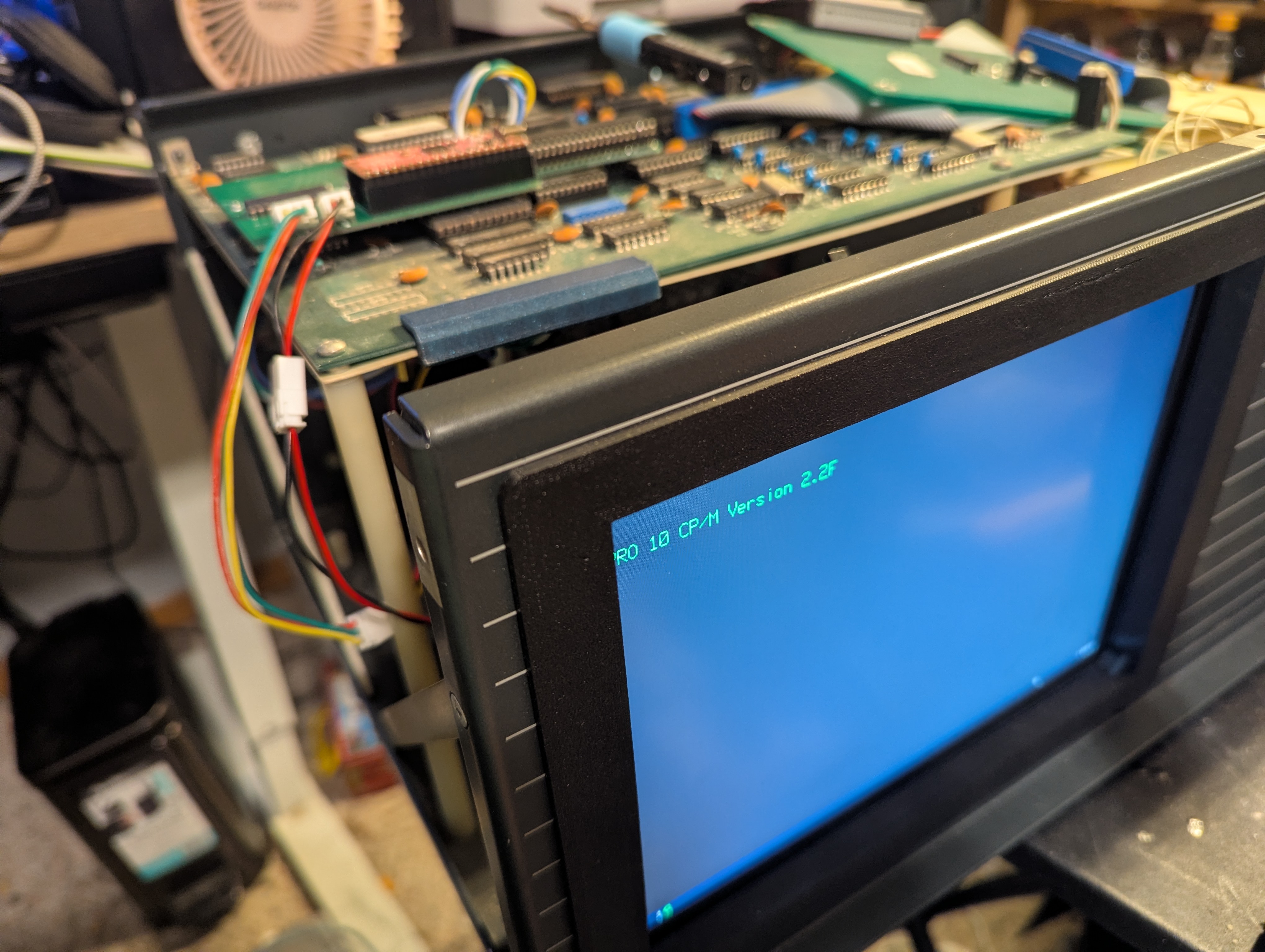
The Kaypro 10 uses a 2732 EPROM as its character ROM (U26) and a Synertek SY6545 CRTC to drive its built-in green phosphor monitor. This project passively taps the character ROM's data outputs and the CRTC's timing signals, reconstructs the pixel data in real time on a Raspberry Pi Pico, and sends it over UART to a Raspberry Pi Zero 2W which renders it to HDMI.
Kaypro 10
├── 6545 CRTC ──── HSYNC, CCLK, VSYNC, DE ──┐
│                                             │
└── 2732 Char ROM ── D0-D7 ──────────────────┤
                                             │
                                    [PCB Shim Board]
                                    74LVCH245 level shifters
                                    100Ω series resistors
                                             │
                                    [Raspberry Pi Pico]
                                    PIO captures ROM data
                                    synced to HSYNC/CCLK
                                             │ UART 3Mbaud
                                    [Raspberry Pi Zero 2W]
                                    Circle bare metal OS
                                    HDMI output
Rotary encoder color controlKaypro10Video/KiCad PCB files for the main capture board. This board sits between the Kaypro motherboard and the character ROM chip (U26), tapping the data lines D0-D7. It also hosts the Raspberry Pi Pico.
Kaypro10VideoShim/KiCad PCB files for the 6545 CRTC shim board. This small board sits between the Kaypro motherboard and the SY6545 CRTC chip, tapping HSYNC, CCLK, VSYNC, and DE without modifying the original board.
PicoKaypro/Raspberry Pi Pico firmware source (C, Pico SDK).
PiDisplay/Raspberry Pi Zero 2W display firmware source (C++, Circle bare metal).
kaypro.cfg)kaypro.palkaypro.uf2Pre-compiled Pico firmware ready to flash.
| Component | Details |
|---|---|
| Raspberry Pi Pico | RP2040, any revision |
| Raspberry Pi Zero 2W | With micro HDMI adapter |
| Kaypro 10 | With SY6545 CRTC and 2732 character ROM |
| Kaypro10Video PCB | See Kaypro10Video/ |
| Kaypro10VideoShim PCB | See Kaypro10VideoShim/ |
| Rotary encoder | 5-pin (CLK, DT, SW, GND, VCC) |
| MicroSD card | For Pi Zero 2W (FAT32, holds kernel and config) |
| Encoder | Pi Zero 2W GPIO | Pin |
|---|---|---|
| CLK | GPIO23 | Pin 16 |
| DT | GPIO24 | Pin 18 |
| SW | GPIO25 | Pin 22 |
| GND | GND | Pin 20 |
| VCC | 3.3V | Pin 17 |
| Pico | Pi Zero 2W GPIO | Function |
|---|---|---|
| GP12 | GPIO15 (Pin 10) | UART TX → RX |
| GND | GND (Pin 6) | Common ground |
PicoKaypro/)Requirements: Pico SDK, CMake, arm-none-eabi-gcc
cd PicoKaypro
mkdir build && cd build
cmake .. \
  -DCMAKE_C_COMPILER=/usr/bin/arm-none-eabi-gcc \
  -DCMAKE_CXX_COMPILER=/usr/bin/arm-none-eabi-g++ \
  -DCMAKE_ASM_COMPILER=/usr/bin/arm-none-eabi-gcc \
  -DPICO_SDK_PATH=/path/to/pico-sdk
make -j4
# Flash kaypro_capture.uf2 to the Pico
Or just flash the pre-built kaypro.uf2 from the repository root.
PiDisplay/)Requirements: Circle bare metal framework, arm-none-eabi-gcc
# Build Circle FatFs addon first (once)
cd circle/addon/fatfs
make RASPPI=2

# Build kernel
cd circle/app/kaypro   # place PiDisplay source here
make RASPPI=2
# Output: kernel7.img
Copy to SD card: kernel7.img, bootcode.bin, start.elf, fixup.dat
Optionally add kaypro.pal for custom colors (see below).
kaypro.cfg (auto-created)Saves current color mode and scanlines state across reboots.
Format: MODE SCANLINES e.g. 1 0 = Amber, scanlines off.
kaypro.pal (optional)Custom color palette. Place in the root of the SD card.
# mode_name  fg_rrggbb  bg_rrggbb
green        00FF46     000000
amber        FFB000     000000
white        FFFFFF     000000
white_blue   FFFFFF     0000AA
rainbow      000000     000000
Colors are 24-bit RGB hex. The rainbow mode ignores fg and generates per-scanline hues automatically.
The SY6545 CRTC on the Kaypro 10 produces the following signals (measured):
| Signal | Frequency | Notes |
|---|---|---|
| CCLK | ~1.286 MHz | Character clock |
| HSYNC | ~21 kHz | HIGH=3µs blanking, LOW=43µs active |
| VSYNC | ~49 Hz | Active low |
| DE | — | Display Enable, active HIGH during active video |
The firmware captures 56 bytes per scan line (the active video window) across 400 total scan lines per frame, giving a frame size of 22,400 bytes transmitted at ~12fps over UART.
MIT License — see LICENSE file for details.
| Qty | Value | Footprint | References |
|---|---|---|---|
| 12 | 100 | Resistor_SMD:R_2010_5025Metric_Pad1.40x2.65mm_HandSolder | R1, R2, R3, R4, R5, R6, R7, R8, R9, R10, R11, R12 |
| 2 | C | Capacitor_THT:C_Disc_D5.0mm_W2.5mm_P5.00mm | C1, C2 |
| 2 | SN74LVC245 | Package_DIP:DIP-20_W7.62mm | U1, U2 |
| 1 | 4k EPROM | Package_DIP:DIP-24_18.0mmx34.29mm_W15.24mm_Socket | U3 |
| 1 | Conn_01x02_Pin | Connector_PinHeader_2.54mm:PinHeader_1x02_P2.54mm_Horizontal | J3 |
| 1 | Conn_01x03_Pin | Connector_PinHeader_2.54mm:PinHeader_1x03_P2.54mm_Horizontal | J1 |
| 1 | Conn_01x04_Pin | Connector_PinHeader_2.54mm:PinHeader_1x04_P2.54mm_Horizontal | J2 |
| 1 | RaspberryPi_Pico | Module:RaspberryPi_Pico_Common_Unspecified | A1 |
| 1 | ~ | Package_DIP:DIP-24_W15.24mm | Header Pins1 |


jabadiagm/MSXhdmi_tn20k
Adaptador hdmi para MSX con Tang Nano 20k


wangyeee/OpenHardware
Collections of hardware design related to my drone project.


It measures 80 × 85 mm and has 2 copper layers, 1.6 mm thick.
22 parts, built around the SN74LVC245AN. The full list of its parts is on this page, with links to each part's symbol and footprint where PCBKit's library has them.
From the jasperhax0r/Kaypro10Video repository on GitHub, at the commit this page was made from: the board is Kaypro10Video/Kaypro10Video.kicad_pcb and its schematic Kaypro10Video/Kaypro10Video.kicad_sch. PCBKit opens the board in the browser, with nothing to install.
Its repository publishes it under the MIT licence: you may reuse it on that licence's terms (keep the author's notice, and for a copyleft licence share your changes alike).