2 layers25.1 × 21.6 mm
DS2502 prog
jamwaffles/optiplower
Power a Dell Optiplex 3050 Micro from a 24V industrial power supply
15 parts33

 jamwaffles/optiplower33
Power a Dell Optiplex 3050 Micro from a 24V industrial power supply
Optiplower is an open-source printed circuit board by jamwaffles, from the jamwaffles/optiplower repository on GitHub. It is a 2-layer board of 56.4 × 21 mm with 22 parts on 15 nets, routed with 80 tracks and 72 vias.
It is built around the DS2502S+, XL4015E1 and LR7533-M, with the UCM1E221MCL1GS, TC33X-2-102E and MDA1050-470M among its other parts. Its parts include 9 capacitors, 4 ICs, 2 resistors, 2 connectors and 1 diode. It belongs with the AVR (ATmega, ATtiny) boards of this library.


Dell Optiplex Power supply experiments.
I want to run a Dell Optiplex 3050 Micro off an industrial 24Vdc supply. Two issues:
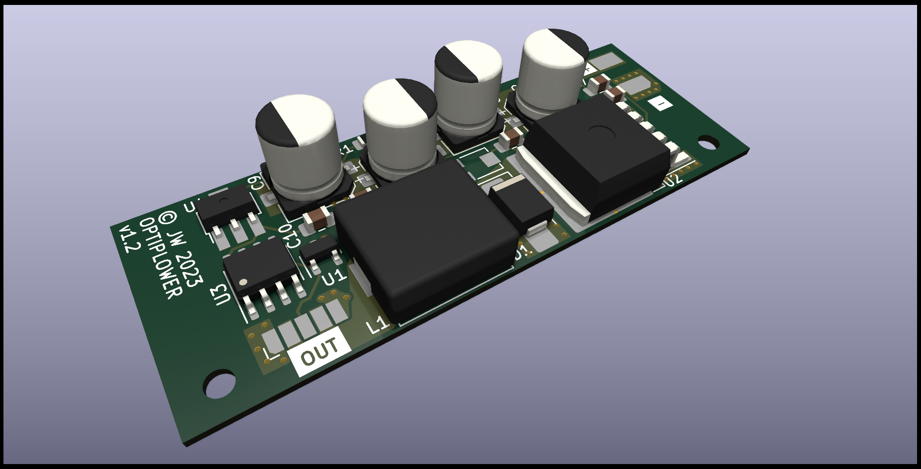
This project aims to solve both by incorporating:
Onto a single, tiny PCB that can be hidden away inside the Dell.
References:
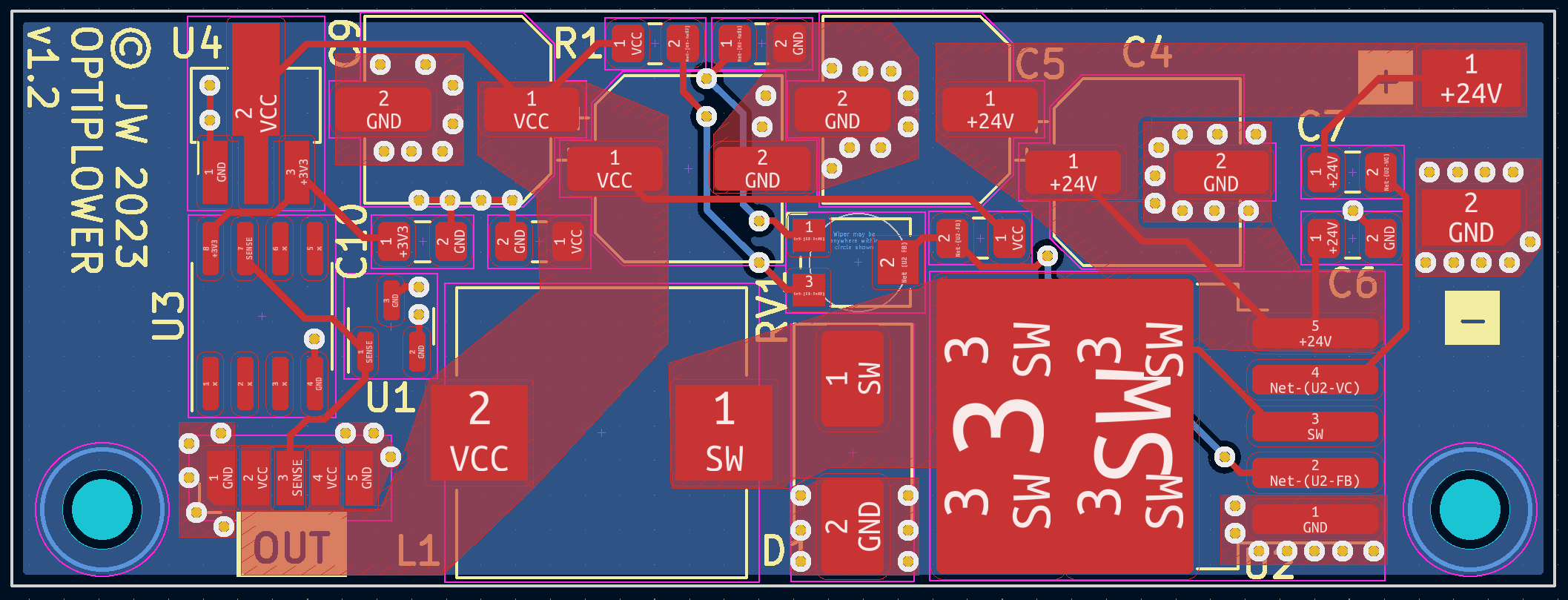
Please use KiCAD 7 to open the board files. The PSU uses JLC/LCSC-sourcable parts if you'd like to build your own.
DigiSpark ATTiny85 devboard LED is connected to PB0
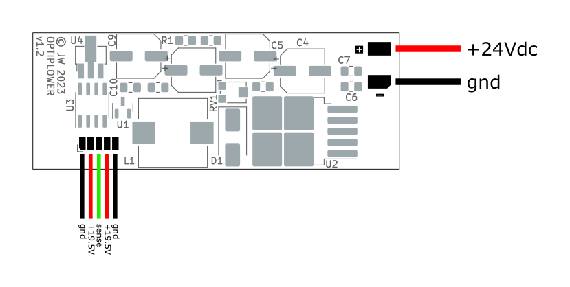
The output connector is designed for a 5-way 1.27mm pitch ribbon cable. The 5 pins mirror the layout of the pins on the barrel jack PCB connector.
DELL00AC090195046CN09T (90w) from
https://github.com/garyStofer/DS2502_DELL_PS/blob/master/DS2502_DELL_PS.ino or
DELL00AC090195046CN09T2157161543835EAL03 with checksum"DELL00AC045195023CN0CDF577243865Q27F2A05=\x94" (45w)Uses Arduino CLI
curl -fsSL https://raw.githubusercontent.com/arduino/arduino-cli/master/install.sh | BINDIR=~/.local/bin shYou'll need to edit the memory variable in ds2502-emulator/src/DS2502.h to change how the
charger identifies.
cd ds2502-emulator

make

make program

make fuses
Works with ATTiny25-10SSU, but can be made to target ATTiny85, etc by modifying the AVRDUDE_MCU?
line in ./ds2502-emulator/Makefile along with the fqbn... line in
./ds2502-emulator/sketch.yaml.
Don't actually need to use the bootloader - I can use the USBASP directly. This section is just left here as a note.
Arduino IDE 2.x, "burn bootloader" with usbasp programmer selected.
Need to swap out programmer for the one on the system or various lib versions won't match, e.g.
error while loading shared libraries: libtinfo.so.5: cannot open shared object file: No such file or directoryE.g.
mv /home/james/.arduino15/packages/arduino/tools/avrdude/6.0.1-arduino5/bin/avrdude /home/james/.arduino15/packages/arduino/tools/avrdude/6.0.1-arduino5/bin/avrdude_old
ln -s $(which avrdude) /home/james/.arduino15/packages/arduino/tools/avrdude/6.0.1-arduino5/bin/avrdude| Qty | Value | Footprint | References |
|---|---|---|---|
| 4 | 1uF | Capacitor_SMD:C_0805_2012Metric_Pad1.18x1.45mm_HandSolder | C6, C7, C10, C12 |
| 4 | 220uF | Capacitor_SMD:CP_Elec_6.3x7.7 | C4, C5, C9, C11 |
| 2 | ~ | MountingHole:MountingHole_2.2mm_M2 | H1, H2 |
| 1 | 10K | Resistor_SMD:R_0805_2012Metric_Pad1.20x1.40mm_HandSolder | R2 |
| 1 | 150K | Resistor_SMD:R_0805_2012Metric_Pad1.20x1.40mm_HandSolder | R1 |
| 1 | 1K | Potentiometer_SMD:Potentiometer_Bourns_TC33X_Vertical | RV1 |
| 1 | 33n | Capacitor_SMD:C_0805_2012Metric_Pad1.18x1.45mm_HandSolder | C8 |
| 1 | 47uH | Optiplower:L_MDA1050_10x11mm | L1 |
| 1 | ATtiny25-10SSU | Package_SO:SOIC-8_3.9x4.9mm_P1.27mm | U3 |
| 1 | Conn_01x02 | Optiplower:5.08_PWR_IN | J1 |
| 1 | Conn_01x03 | Optiplower:Output_pads | J2 |
| 1 | DS2502S+ | Package_TO_SOT_SMD:SOT-23 | U1 |
| 1 | LR7533-M | Package_TO_SOT_SMD:SOT-89-3_Handsoldering | U4 |
| 1 | SK84B | Diode_SMD:D_SMB_Handsoldering | D1 |
| 1 | XL4015 | Package_TO_SOT_SMD:TO-263-5_TabPin3 | U2 |
jamwaffles/optiplower
Power a Dell Optiplex 3050 Micro from a 24V industrial power supply


MIT-Senseable-City-Lab/flatburn-lte
Part of the City Scanner project at MIT Senseable City Lab, Flatburn is an open-source, solar-powered, modular sensing platform that can be easily deployed on road vehicles to collect various environmental data.


Takazudo/zudo-osc-hole-field
This directory retains the rejected #38 nine-board-era schematic, PCB and route receipts at base commit 1fc6e5347308fe5e8166d5828ba3ba6fa8e101c7. It is excluded from the current ten-board manifest.


GonzaCerv/noah-hardware
This repo contains all the hardware description for the Noah project. Here lies 3D models, electronics PCB and Firmware software of the robot.

SRA-VJTI/Evo-Borne
This repository focuses on building an open-source morphobot.
It measures 56.4 × 21 mm and has 2 copper layers, 0.8 mm thick.
22 parts, built around the DS2502S+, XL4015E1, LR7533-M and UCM1E221MCL1GS. The full list of its parts is on this page, with links to each part's symbol and footprint where PCBKit's library has them.
From the jamwaffles/optiplower repository on GitHub, at the commit this page was made from: the board is hardware/optiplower.kicad_pcb and its schematic DS2502_prog/DS2502_prog.kicad_sch. PCBKit opens the board in the browser, with nothing to install.
Its repository states no licence, so its author keeps all rights: ask jamwaffles before reusing the design.