

2 layers228.4 × 85 mm
LeChiffre
tominabox1/Le-Chiffre-Keyboard
Great thanks goes to Jake at P3D for really making the case amazing and open sourcing his work. Check him out at P3Dstore.com
105 parts183GPL-3.0
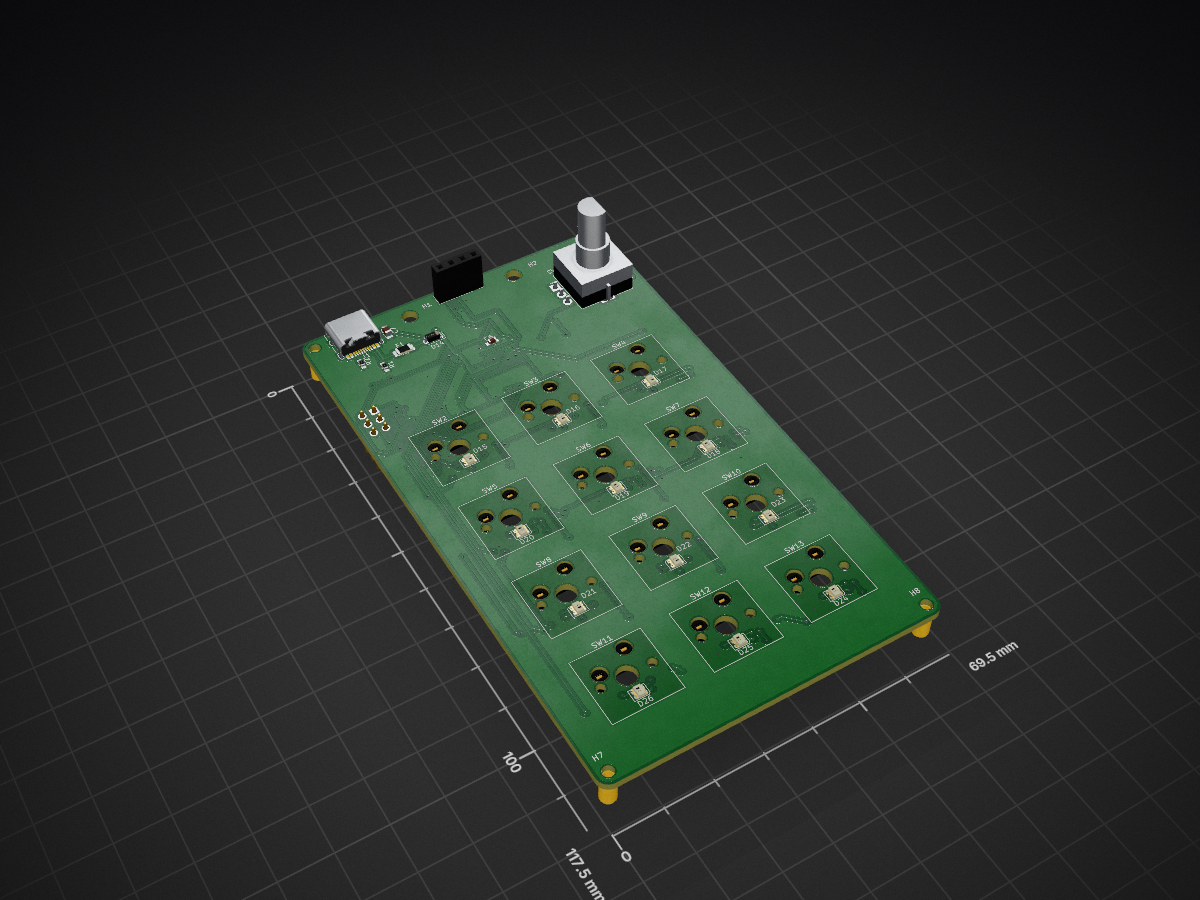
 Jakov4848/CustomMacroDeck1
A custom macropad project featuring custom PCB design, laser-cut enclosure, and dedicated firmware implementation.
Macropad is an open-source printed circuit board by Jakov4848, from the Jakov4848/CustomMacroDeck repository on GitHub. It is a 2-layer board of 69.5 × 117.5 mm with 87 parts on 71 nets, routed with 806 tracks and 184 vias.
It is built around the ATMEGA32U4-AU and WS2812B. Its parts include 27 diodes, 22 capacitors, 14 switches, 12 resistors and 3 connectors. It belongs with the keyboards and input boards and the AVR (ATmega, ATtiny) boards of this library.
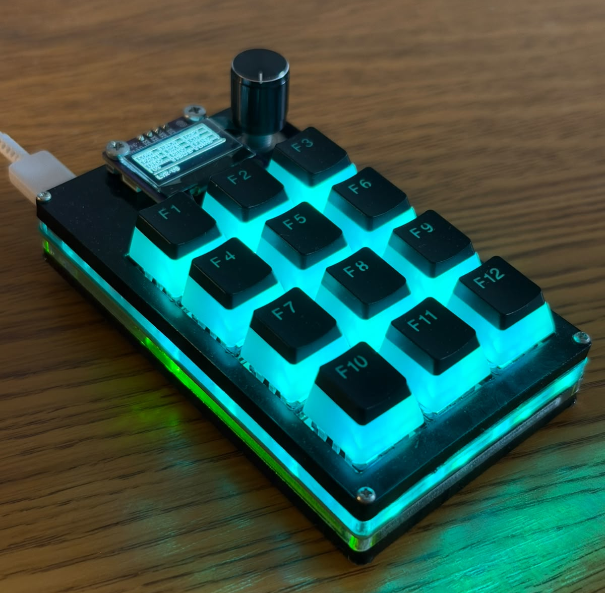
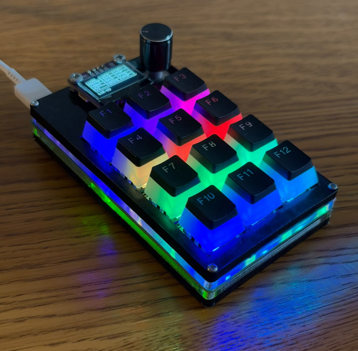
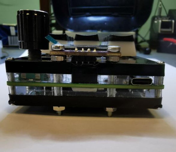
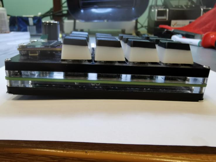
This repository contains the hardware and software files for an open-source, programmable macropad keyboard based on the Arduino platform. Developed as a bachelor's thesis, this device allows users to store keyboard shortcuts directly on the hardware's memory, eliminating the need for complex PC software while improving daily workflow productivity.
The custom PCB was designed in KiCad. If you are assembling the board yourself, you will need the following components:
| Component | Description / Package | Quantity |
|---|---|---|
| Microcontroller | ATmega32U4-AU (QFP-44 10x10) | 1 |
| USB Connector | USB 2.0 Type-C Receptacle 16-pin (SMD) | 1 |
| Display | 0.96" OLED I2C SSD1306 (30x30) | 1 |
| Rotary Encoder | EC11 Rotary Switch (THT) | 1 |
| Mechanical Switches | Cherry MX Keyswitches (THT) | 12 |
| Hot-Swap Sockets | CPG151101S11-2 (SMD) | 12 |
| RGB Lighting LEDs | WS2812B NeoPixel LEDs | 12 |
| Anti-Ghosting Diodes | 1N4148W 75V 150mA (SOD-123) | 12 |
| Reset Switch | Tactile Switch 6.1x3.6mm (TS-1092S-B3D2-G) | 1 |
| Crystal Oscillator | 16.000MHz SMD5032-2P (ABM3-16.000MHZ-D2Y-T) | 1 |
| Protection | Schottky Diode 20V 500mA (MBR0520LT1G) | 1 |
| Protection | Polymeric PTC Resettable Fuse 6V 500mA (SMD1206P050TF) | 1 |
| LED (Indication) | Blue 460nm LED (0603) | 1 |
| Resistors (0603) | 1kΩ (x1), 2.2kΩ (x2), 5.1kΩ (x2), 10kΩ (x2), 470Ω (x2), 22Ω (x2) | 11 Total |
| Capacitors (0603/0805) | 100nF (x6), 10uF (x1), 1uF (x1), 22pF (x2) | 10 Total |
USBasp programmer is required to flash the initial bootloader to the ATmega32U4 chip using the ISP (In-System Programming) header.The macropad operates on a Finite-State Machine with 8 distinct modes (states):
When the device is in PROG MODE, open the Arduino IDE Serial Monitor (or use a serial Python script) to send UART commands. Due to the 1KB EEPROM limit, each macro is restricted to a maximum of 10 sequential keystrokes.
{{layer_id, layer_name}}<<layer_id, key_id, label, macro_steps>>?Whenever a programmed key is pressed in normal mode, a pop-up appears on the OLED display showing the executed shortcut (e.g., CTRL+F).
| Qty | Value | Footprint | References |
|---|---|---|---|
| 18 | 0.1uF | Capacitor_SMD:C_0603_1608Metric_Pad1.08x0.95mm_HandSolder | C4, C5, C6, C10, C11, C12, C13, C14, C15, C16, C17, C18, C19, C20, C21, C22 +2 |
| 12 | D | Diode_SMD:D_SOD-123 | D1, D2, D3, D4, D5, D6, D7, D8, D9, D10, D11, D12 |
| 12 | SW_Push | PCM_Switch_Keyboard_Hotswap_Kailh:SW_Hotswap_Kailh_MX_1.00u | SW2, SW3, SW4, SW5, SW6, SW7, SW8, SW9, SW10, SW11, SW12, SW13 |
| 12 | WS2812B | Library:LED_WS2812B-2020_PLCC4_2.0x2.0mm_edited | D15, D16, D17, D18, D19, D20, D21, D22, D23, D24, D25, D26 |
| 4 | MountingHole | MountingHole:MountingHole_2.2mm_M2 | H5, H6, H7, H8 |
| 2 | 10K | Resistor_SMD:R_0603_1608Metric_Pad0.98x0.95mm_HandSolder | R5, R6 |
| 2 | 1K | Resistor_SMD:R_0603_1608Metric_Pad0.98x0.95mm_HandSolder | R7, R12 |
| 2 | 22 | Resistor_SMD:R_0603_1608Metric_Pad0.98x0.95mm_HandSolder | R3, R4 |
| 2 | 22pF | Capacitor_SMD:C_0603_1608Metric_Pad1.08x0.95mm_HandSolder | C2, C3 |
| 2 | 470ohm | Resistor_SMD:R_0603_1608Metric_Pad0.98x0.95mm_HandSolder | R10, R11 |
| 2 | 5.1K | Resistor_SMD:R_0603_1608Metric_Pad0.98x0.95mm_HandSolder | R1, R2 |
| 2 | LED | LED_SMD:LED_0603_1608Metric_Pad1.05x0.95mm_HandSolder | D13, D27 |
| 2 | MountingHole | MountingHole:MountingHole_3.2mm_M3 | H1, H2 |
| 2 | R | Resistor_SMD:R_0603_1608Metric_Pad0.98x0.95mm_HandSolder | R8, R9 |
| 1 | 10uF | Capacitor_SMD:C_0805_2012Metric_Pad1.18x1.45mm_HandSolder | C7 |
| 1 | 1uF | Capacitor_SMD:C_0603_1608Metric_Pad1.08x0.95mm_HandSolder | C1 |
| 1 | ATmega32U4-A | Package_QFP:TQFP-44_10x10mm_P0.8mm | U1 |
| 1 | Conn_01x04 | Connector_PinSocket_2.54mm:PinSocket_1x04_P2.54mm_Vertical | J2 |
| 1 | Conn_02x03_Top_Bottom | Connector_PinHeader_2.54mm:PinHeader_2x03_P2.54mm_Vertical | J3 |
| 1 | Crystal | Crystal:Crystal_SMD_Abracon_ABM3-2Pin_5.0x3.2mm_HandSoldering | Y1 |
| 1 | D_Schottky | Diode_SMD:D_SOD-123 | D14 |
| 1 | Fuse | Fuse:Fuse_1206_3216Metric_Pad1.42x1.75mm_HandSolder | F1 |
| 1 | RotaryEncoder_Switch | Rotary_Encoder:RotaryEncoder_Alps_EC11E-Switch_Vertical_H20mm_MountingHoles | SW14 |
| 1 | SW_Push | Button_Switch_SMD:SW_SPST_CK_RS282G05A3 | SW1 |
| 1 | USB_C_Receptacle_USB2.0_16P | Connector_USB:USB_C_Receptacle_HRO_TYPE-C-31-M-12 | J1 |
It measures 69.5 × 117.5 mm and has 2 copper layers, 1.6 mm thick.
87 parts, built around the ATMEGA32U4-AU and WS2812B. The full list of its parts is on this page, with links to each part's symbol and footprint where PCBKit's library has them.
From the Jakov4848/CustomMacroDeck repository on GitHub, at the commit this page was made from: the board is kicad_files/macropad.kicad_pcb and its schematic kicad_files/RGB_LEDs.kicad_sch. PCBKit opens the board in the browser, with nothing to install.
Its repository states no licence, so its author keeps all rights: ask Jakov4848 before reusing the design.
tominabox1/Le-Chiffre-Keyboard
Great thanks goes to Jake at P3D for really making the case amazing and open sourcing his work. Check him out at P3Dstore.com

The-Royal/The_Royal_Open-Source-Projects
A Master Repository For All things Royal Made

cester-ino/OTTO-hardware
those specs refer to the tactile buttons version, but a led backlight button version is in the works too.

sadekbaroudi/euclid36
At the time of creation, using Kicad 5.1.9 - This may not work with future versions


Maxr1998/Pulse_4k
CAD files for plate and PCB of my Pulse 4k macropad, with 4 keys and 2 rotary encoders.

misonoworks/chocolate-bar
A low-profile 50% keyboard, with less ergonomics than expected!
