2 layers48 × 107 mm

 Jakob30/Robot4Workshop1
Dieses Projekt beschreibt den Aufbau und die Inbetriebnahme eines Roboterarms, der mithilfe von 3D-gedruckten Teilen, einer selbstgefertigten Platine und einem STM32F4-Mikrocontroller gesteuert wird.
PCB Layout is an open-source printed circuit board by Jakob30, from the Jakob30/Robot4Workshop repository on GitHub. It is a 2-layer board of 165 × 115 mm with 76 parts on 155 nets, routed with 778 tracks and 230 vias.
Its parts include 23 resistors and 10 capacitors.
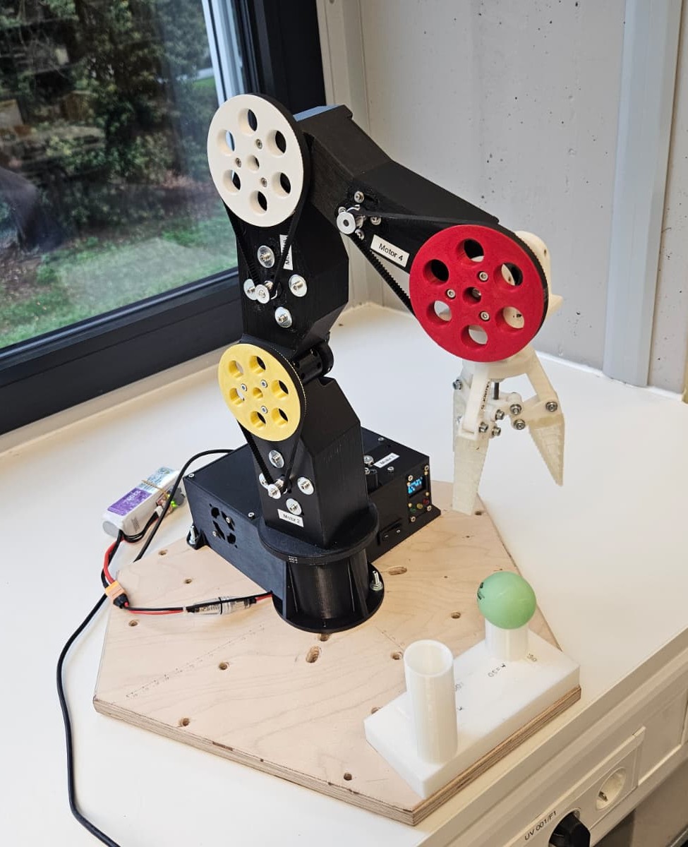
Dieses Projekt beschreibt den Aufbau und die Inbetriebnahme eines Roboterarms, der mithilfe von 3D-gedruckten Teilen, einer selbstgefertigten Platine und einem STM32F4-Mikrocontroller gesteuert wird.
3D-Druckteile
Bestellung von Bauteilen
Wenn alle 3D-Druckteile und Bauteile vorhanden sind, den Arm gemäß der Montageanleitung zusammenbauen.
Fertigung
Bestückung
Stromversorgung
Setup
Stromversorgung
Anpassung
main.c programmiert und alle aufzurufenden Funktionen sind in README beschrieben.Vor der ersten Inbetriebnahme ist eine Kalibrierung der StallGuard-Werte notwendig.
Empfohlen wird die Nutzung von STM32CubeMonitor, um Variablen in Echtzeit auszulesen.
Wichtige Parameter:
STALL_BUFFER_M_XLOW_COUNTER_THRESHOLD_M_XSTALL_MAX_M_XEinen Eindruck, wie der fertige Roboterarm aussehen kann, gibt es hier:
➡️ Video ansehen
| Qty | Value | Footprint | References |
|---|---|---|---|
| 20 | Conn_01x02_Pin | Connector_PinHeader_2.54mm:PinHeader_1x02_P2.54mm_Vertical_SMD_Pin1Left | Driver1_MS1, Driver1_MS2, Driver1_Rx1, Driver1_Tx1, Driver2_MS1, Driver2_MS2, Driver2_Rx1, Driver2_Tx1, Driver3_MS1, Driver3_MS2, Driver3_Rx1, Driver3_Tx1, Driver4_MS1, Driver4_MS2, Driver4_Rx1, Driver4_Tx1 +4 |
| 15 | 10k | Resistor_SMD:R_1206_3216Metric_Pad1.30x1.75mm_HandSolder | R1, R2, R3, R4, R7, R8, R9, R10, R11, R12, R15, R16, R17, R18, R20 |
| 5 | 10u | Capacitor_SMD:C_1206_3216Metric_Pad1.33x1.80mm_HandSolder | C2, C4, C6, C8, C10 |
| 5 | 1k | Resistor_SMD:R_1206_3216Metric_Pad1.30x1.75mm_HandSolder | R5, R6, R13, R14, R19 |
| 5 | 47u | Capacitor_SMD:C_1206_3216Metric_Pad1.33x1.80mm_HandSolder | C1, C3, C5, C7, C9 |
| 5 | Conn_01x02_Socket | Connector_PinSocket_2.54mm:PinSocket_1x02_P2.54mm_Vertical_SMD_Pin1Left | Bypass_C1, Bypass_C2, Bypass_C3, Bypass_C4, Bypass_C5 |
| 5 | Conn_01x04_Socket | Connector_PinSocket_2.54mm:PinSocket_1x04_P2.54mm_Vertical | Motor_Headerpin_1, Motor_Headerpin_2, Motor_Headerpin_3, Motor_Headerpin_4, Motor_Headerpin_5 |
| 3 | 180 | Resistor_SMD:R_1206_3216Metric_Pad1.30x1.75mm_HandSolder | R21, R22, R23 |
| 3 | LED | LED_THT:LED_D5.0mm | LED_green1, LED_red1, LED_yellow1 |
| 1 | 0,96_OLED_display | OLED_Display:0,96_OLED_Display | Display1 |
| 1 | Conn_01x02_Pin | Connector_AMASS:AMASS_XT60-M_1x02_P7.20mm_Vertical | PowerSupplyConnector1 |
| 1 | NUCLEO-F446RE | NUCLEO-F446RE:MODULE_NUCLEO-F446RE | MCU1 |
| 1 | Screw_Terminal_01x02 | my_custom_footprint:DC_DC_Converter_with_Screw_Terminal | DCDC_Output1 |
| 1 | Screw_Terminal_01x02 | TerminalBlock_Phoenix:TerminalBlock_Phoenix_PT-1,5-2-5.0-H_1x02_P5.00mm_Horizontal | DCDC_Input1 |
| 1 | TMC2209_Driver_1 | TMC2209_SILENTSTEPSTICK:MODULE_TMC2209_SILENTSTEPSTICK | Driver_1 |
| 1 | TMC2209_Driver_2 | TMC2209_SILENTSTEPSTICK:MODULE_TMC2209_SILENTSTEPSTICK | Driver_2 |
| 1 | TMC2209_Driver_3 | TMC2209_SILENTSTEPSTICK:MODULE_TMC2209_SILENTSTEPSTICK | Driver_3 |
| 1 | TMC2209_Driver_4 | TMC2209_SILENTSTEPSTICK:MODULE_TMC2209_SILENTSTEPSTICK | Driver_4 |
| 1 | TMC2209_Driver_5 | TMC2209_SILENTSTEPSTICK:MODULE_TMC2209_SILENTSTEPSTICK | Driver__5 |

joeycastillo/The-Open-Book
For details on how to build, test and use Open Book, I've made documentation available here.

hoglet67/RGBtoHDMI
Bare-metal Raspberry Pi project that provides pixel-perfect sampling of Retro Computer RGB/YUV video and conversion to HDMI

jpconstantineau/ErgoTravel
A Portable Ergonomic Split Keyboard inspired from the ErgoDox, Let's Split and Minidox

CRImier/MyKiCad
My KiCad boards. Can't be bothered uploading individually anymore, so here you go.

Teslafly/Dead-OpenBMS-dead
A scalable, open source battery management system

profdc9/RFBitBanger
A QRP digital transceiver created from readily available parts for off-the-grid maintenance

katbinaris/nanofoc_devkit
Compact All-In-One BLDC Controler featuiring ESP32-S3, TMC6300 and Magalpha sensors. Small 35x35mm footprint.
It measures 165 × 115 mm and has 2 copper layers, 1.6 mm thick.
76 parts. The full list of its parts is on this page, with links to each part's symbol and footprint where PCBKit's library has them.
From the Jakob30/Robot4Workshop repository on GitHub, at the commit this page was made from: the board is Elektronik/PCB_Layout/PCB_Layout.kicad_pcb and its schematic Elektronik/PCB_Layout/PCB_Layout.kicad_sch. PCBKit opens the board in the browser, with nothing to install.
Its repository states no licence, so its author keeps all rights: ask Jakob30 before reusing the design.