
2 layers40.8 × 80 mm
Devkit2
jacobjuneau6/devkit2
A compact ESP32-S3 development board designed for rapid prototyping and embedded projects.
13 partsMIT
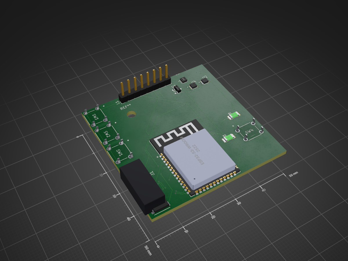
A simple ESP32-S3 based phone companion and pocket computer. This open-source hardware project includes a custom PCB, 3D-printable case, and Arduino firmware — everything you need to build a portable device with a color…
PDA is an open-source printed circuit board by jacobjuneau6, from the jacobjuneau6/PDA repository on GitHub, published under the MIT licence. It is a 2-layer board of 50 × 50 mm with 16 parts on 55 nets, routed with 314 tracks and 58 vias.
It is built around the ESP32-S3-WROOM-1-N16R8, AO3400A and TPS74533PCQWDRVRQ1, with the B3F-1002 and COM-16347 among its other parts. Its parts include 5 ICs, 4 switches, 2 resistors, 2 connectors and 1 diode. It belongs with the ESP32 boards of this library.


A simple ESP32-S3 based phone companion and pocket computer. This open-source hardware project includes a custom PCB, 3D-printable case, and Arduino firmware — everything you need to build a portable device with a color TFT display, LiPo battery management, and physical navigation buttons.
| Silkscreen | GPIO | Function |
|---|---|---|
| SCL | 2 | SPI SCLK (TFT clock) |
| SDA | 1 | SPI MOSI (TFT data) |
| CS | 3 | TFT chip select |
| DC | 4 | TFT data/command |
| RST | 5 | TFT reset |
| BL | 6 | TFT backlight PWM |
| — | 7 | WS2812 status LED (NeoPixel) |
| — | 8 | I2C SCL (MAX17048 fuel gauge) |
| — | 9 | I2C SDA (MAX17048 fuel gauge) |
| — | 10 | Button UP |
| — | 11 | Button SELECT |
| — | 12 | Button DOWN |
Display connector: 1×08 pin header (GND, VCC, SCL, SDA, RST, DC, CS, BL) for ST7789 240×320 TFT, 1.54″ or 1.69″ diagonal.
I²C address: MAX17048 at 0x36.
| Reference | Qty | Part | DigiKey P/N | Description | Price |
|---|---|---|---|---|---|
| J1 | 1 | RAHMB20AUETR | 137-RAHMB20AUETRCT-ND | USB micro-B receptacle, right-angle, SMT (Switchcraft) | |
| LED1 | 1 | COM-16347 | 568-16347CT-ND | WS2812/NeoPixel RGB LED | |
| R1, R2 | 2 | RC1206FR-132KL | 13-RC1206FR-132KLCT-ND | 2 kΩ 1206 thick-film resistor (Yageo) | |
| SW1, SW2, SW3, SW4 | 4 | B3F-1002 | SW401-ND | Tactile switch (Omron) | |
| U1 | 1 | ESP32-S3-WROOM-1-N16R8 | 5407-ESP32-S3-WROOM-1-N16R8CT-ND | ESP32-S3 module, 16 MB flash, 8 MB PSRAM | |
| U2 | 1 | MCP73831T-2DCI/MC | MCP73831T-2DCI/MCCT-ND | Li-Ion/Li-Po battery charger IC (Microchip) | |
| U3 | 1 | TPS74533PCQWDRVRQ1 | 296-TPS74533PCQWDRVRQ1CT-ND | 3.3 V LDO voltage regulator, 500 mA (TI) | |
| U4 | 1 | MAX17048G+T10 | MAX17048G+T10CT-ND | LiPo fuel gauge IC (Maxim Integrated) | |
| U5 | 1 | AO3400A | 785-1000-1-ND | N-channel MOSFET, SOT-23 (battery protection) | |
| — | 1 | Custom PCB & stencil | JLCPCB | Fabrication | $20.00 |
| — | 1 | DigiKey components | Components & shipping | $30.00 | |
| — | 1 | 1Ah battery | https://www.amazon.com/dp/B0DPZVBKMY?th=1 | $8.00 | |
| — | 1 | Display | https://www.amazon.com/gp/product/B0DFWLD38D/ref=ox_sc_act_title_2?smid=A2UYBS1CH53PM5 | $16.00 |
USB VBUS (5 V)
  ├── MCP73831 charger (U2) ──→ VBAT (battery voltage)
  │     ├── AO3400A MOSFET (U5) — battery protection
  │     └── MAX17048 fuel gauge (U4) — I²C monitoring
  │
  └── TPS74533 LDO (U3) ──→ 3.3 V rail
        ├── ESP32-S3 module (U1)
        ├── Display backlight (PWM on GPIO6)
└── Peripherals (WS2812, buttons, I²C pull-ups)PDA/
├── README.md # This file
├── BOM.csv # Bill of Materials with DigiKey part numbers
├── Journal.md # Design journal — case design notes & images
├── LICENSE # MIT License
│
├── board/ # KiCad PCB design
│ ├── board.kicad_sch # Schematic
│ ├── board.kicad_pcb # PCB layout
│ ├── board.kicad_pro # Project settings
│ ├── gbrs/ # Gerber files (ready for fabrication)
│ └── staging/ # Vendor symbols, footprints, and 3D models
│
├── CAD/ # FreeCAD mechanical design
│ ├── Assembly.FCStd # Full assembly (PCB + case + battery + display)
│ ├── case.FCStd # 3D-printable enclosure
│ ├── battery.FCStd # Dummy battery model (fit check)
│ ├── display.FCStd # Dummy display model (fit check)
│ └── PCB.step # PCB STEP export
│
└── CODE/ # Firmware
└── test/
├── platformio.ini # PlatformIO build configuration
└── src/
└── main.cpp # Arduino demo sketchThe demo firmware exercises all major subsystems: display, battery gauge, status LED, and buttons.
Prerequisites: PlatformIO (VS Code extension or CLI).
cd CODE/test

# Build
pio run

# Flash and open serial monitor (115200 baud)
pio run --target upload --target monitor| Library | Version |
|---|---|
| Adafruit GFX | ≥1.11 |
| Adafruit ST7735/ST7789 | ≥1.10 |
| Adafruit MAX1704X | ≥1.0 |
| FastLED | ≥3.7 |
All are fetched automatically by PlatformIO via lib_deps.
| Setting | Value |
|---|---|
| Board | ESP32-S3 DevKitC-1 |
| Framework | Arduino |
| Monitor baud | 115200 |
backlightWrite(0..255) in loop() (e.g., dim after inactivity)tft.setRotation(1) (0–3) if your panel is mounted differentlyI2C_SDA and I2C_SCL at the top of main.cppboard/gbrs/The PCB uses all surface-mount components. Most ICs are in small-outline packages (SOT-23, TDFN, WSON). The display connects via a standard 1×08 2.54 mm pitch pin header.
Designed in FreeCAD with a boxy, sharp-edged aesthetic. The case holds:
Dummy battery and display models are included for fit checking in the assembly.
MIT License — see LICENSE for details.
Copyright (c) 2026 jacobjuneau6
| Qty | Value | Footprint | References |
|---|---|---|---|
| 4 | B3F-1002 | footprints:SW_B3F-1000_OMR | SW1, SW2, SW3, SW4 |
| 2 | RC1206FR-132KL | footprints:RESC3216X65 | R1, R2 |
| 1 | AO3400A | Package_TO_SOT_SMD:SOT-23 | U5 |
| 1 | COM-16347 | footprints:COM-16347_SPK | LED1 |
| 1 | ESP32-S3-WROOM-1-N16R8 | footprints:ESP32-S3-WROOM-1_EXP | U1 |
| 1 | MAX17048G_T10 | footprints:SON50P200X200X80-9N | U4 |
| 1 | MCP73831T-2DCI_MC | footprints:SON50P200X200X80-9N | U2 |
| 1 | PINHD_1x2_Male | Connector_PinHeader_2.54mm:PinHeader_1x02_P2.54mm_Vertical_SMD_Pin1Left | J2 |
| 1 | RAHMB20AUETR | footprints:SWITCHCRAFT_RAHMB20AUETR | J1 |
| 1 | TPS74533PCQWDRVRQ1 | easyeda2kicad:WSON-6_L2.0-W2.0-P0.65-TL-EP | U3 |
| 1 | ~ | Connector_PinHeader_2.54mm:PinHeader_1x08_P2.54mm_Vertical | L1 |
The 15 most common of 16 parts.
It measures 50 × 50 mm and has 2 copper layers, 1.6 mm thick.
16 parts, built around the ESP32-S3-WROOM-1-N16R8, AO3400A, TPS74533PCQWDRVRQ1 and B3F-1002. The full list of its parts is on this page, with links to each part's symbol and footprint where PCBKit's library has them.
From the jacobjuneau6/PDA repository on GitHub, at the commit this page was made from: the board is board/board.kicad_pcb and its schematic board/board.kicad_sch. PCBKit opens the board in the browser, with nothing to install.
Its repository publishes it under the MIT licence: you may reuse it on that licence's terms (keep the author's notice, and for a copyleft licence share your changes alike).
jacobjuneau6/devkit2
A compact ESP32-S3 development board designed for rapid prototyping and embedded projects.


Dxem/Learning-pcb-design
Im learning pcb design - so everything i do in this repo is open source and you are free to use this designs

open-ephys/ECP5U85-BSE-USB-IO-Tester
IO Test board for ECP5U85-BSE-USB

FranciscoCamara/PCB-Design-Course
Course materials and projects for learning PCB design


open-ephys/oe-acquisition-board-gen3
3rd Generation Open Ephys USB Acquisition Board