Skip to the content
PCBKitNew board
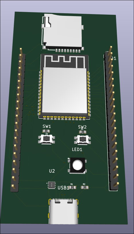
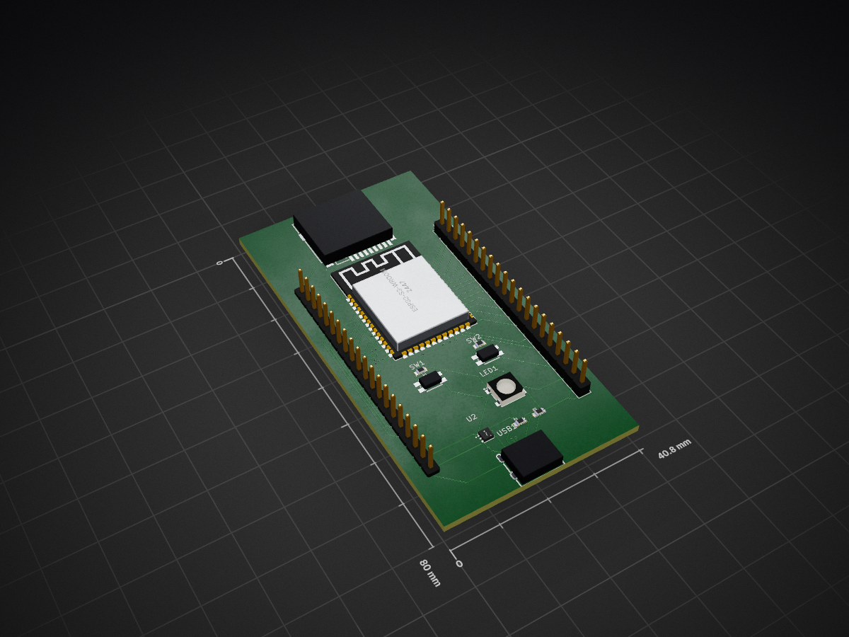
2 layers40.8 × 80 mmDevkit2, the printed circuit board in 3D

A compact ESP32-S3 development board designed for rapid prototyping and embedded projects.

Size
40.8 × 80 mm
Copper layers
2
Thickness
1.6 mm
Parts
13
Nets
61
Pads
149
Tracks, vias
348, 36
Routed
Yes
KiCad
KiCad 10.0 (file 20260206)
Created
28 Jun 2026
Updated
9 Jul 2026

Overview

Devkit2 is an open-source printed circuit board by jacobjuneau6, from the jacobjuneau6/devkit2 repository on GitHub, published under the MIT licence. It is a 2-layer board of 40.8 × 80 mm with 13 parts on 61 nets, routed with 348 tracks and 36 vias.

It is built around the ESP32-S3-WROOM-1-N8R8, TPS74533PCQWDRVRQ1 and KMR221NGLFS, with the RP0603BRE0710KL, RT0603BRE075K1L and WS2812B-B/T among its other parts. Its parts include 4 resistors, 2 ICs, 2 connectors, 2 switches and 1 diode. It belongs with the ESP32 boards of this library.

Main components

6

README

README.md

devkit2

A compact ESP32-S3 development board designed for rapid prototyping and embedded projects.

Features

  • ESP32-S3-WROOM-1 module — dual-core Xtensa LX7, 2.4 GHz Wi-Fi, BLE 5.0, 8 MB PSRAM, 16 MB Flash
  • USB-C connector for power, programming, and serial monitor
  • WS2812B addressable RGB LED on GPIO 2
  • microSD card slot (TF-PUSH) connected via SPI
  • 2× tactile push buttons — Boot (GPIO 0) and Reset (EN)
  • 2× 20-pin breakout headers bringing out all available GPIO, power rails, and peripheral signals
  • 3.3 V LDO regulator (TPS74533) — up to 500 mA output, 6.5 V max input
  • Compact form factor — fits on a breadboard with one row of pins free on each side

devkit2 3D render

Pin Map

text
                    ┌──────────────────┐
             3.3V —│ J1               │— GND
             EN   —│                  │— VIN (5 V)
            IO4   —│                  │— IO5
            IO6   —│                  │— IO7
            IO15  —│                  │— IO8
            IO16  —│                  │— IO9
            IO17  —│                  │— IO10
            IO18  —│                  │— IO11
            IO19  —│                  │— IO12
            IO20  —│                  │— IO13
            IO21  —│    ESP32-S3      │— IO14
            IO26  —│    devkit2       │— IO38
            IO35  —│                  │— IO39
            IO36  —│                  │— IO40
            IO37  —│                  │— IO41
            IO42  —│                  │— IO45
            IO43  —│                  │— IO46
            IO44  —│                  │— IO47
            GND   —│                  │— IO2  (onboard LED)
            5 V   —│                  │— IO0  (Boot button)
                   └──────────────────┘
PeripheralGPIONotes
WS2812B LED2DIN, use NeoPixel lib
Boot button0Pull LOW to enter download mode
Reset buttonENPulls EN pin LOW
microSD CS5SPI chip select
microSD MOSI11SPI data
microSD MISO13SPI data
microSD SCK12SPI clock

Getting Started

1. Add Board Support

Install the esp32 board package by Espressif in the Arduino IDE:

  1. Open File → Preferences
  2. Add this URL to Additional Boards Manager URLs:
    text
    https://espressif.github.io/arduino-esp32/package_esp32_index.json
  3. Open Tools → Board → Boards Manager, search for esp32, and install esp32 by Espressif Systems

2. Select Board Settings

SettingValue
BoardESP32S3 Dev Module
USB CDC On BootEnabled
Flash Size16 MB (128 Mb)
PSRAMOPI PSRAM
Upload ModeUART / Hardware CDC

3. Install Libraries

Install these libraries via Tools → Manage Libraries:

  • Adafruit NeoPixel — for the onboard WS2812B LED
  • SD (built-in, or SdFat) — for the microSD slot

4. Upload the Demo

Hold Boot (SW1), press and release Reset (SW2), then release Boot to enter download mode. Open CODE/demo/demo.ino in the Arduino IDE, select the correct port, and hit Upload.

Bill of Materials

DesignatorQtyValueFootprintLCSC #
U11ESP32-S3-WROOM-1WIRELM-SMD ESP32-S3-WROOM-1C2913201
U21TPS74533PCQWDRVRQ1WSON-6 2.0×2.0 mmC2860924
USB11TYPE-C 16PIN 2MDUSB-C SMD 16-pinC2765186
LED11WS2812B-B/WLED-SMD 5.0×5.0 mmC2761795
CARD11TF PUSHTF-SMD push-pushC393941
J1, J22PINHD 1×20 MalePinHeader 1×20 2.54 mm—
SW1, SW22KMR221NGLFSKEY-SMD 4.2×2.8 mmC269272
R1, R22RT0603BRE075K1L0603 (1608 Metric)C728607
R3, R42RT0603BRE0710KL0603 (1608 Metric)C6277183
  • R1, R2 = 5.1 kΩ thin-film — USB-C CC pull-downs
  • R3, R4 = 10 kΩ thick-film — EN and BOOT pull-ups
  • SW1 = Reset, SW2 = Boot
  • All passives are 0603 imperial (1608 metric)

Hardware

2026-07-08-13-45-30-922 2026-07-08-13-45-50-782

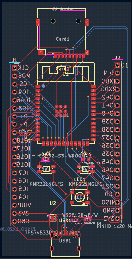
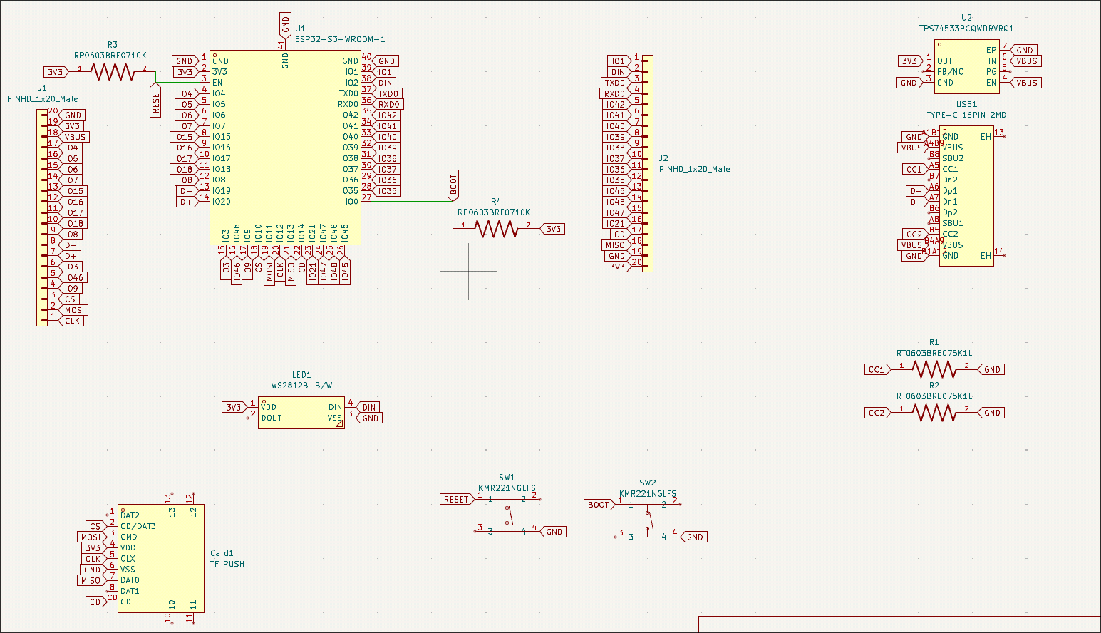
Board files live in BOARD/. The project was designed in KiCad 8.

🔗 View schematic & PCB interactively on KiCanvas

PCB layout

Schematic

DirectoryContents
BOARD/Board/Schematic, PCB, project files
BOARD/Board/gbrs/Gerber files (JLCPCB ready)
BOARD/Board/production/BOM, CPL, netlist
BOARD/CAD/3D STEP model

License

Hardware and software are released under the MIT License.


Built by jacobjuneau6

Parts

13
QtyValueFootprintReferences
2KMR221NGLFSeasyeda2kicad:KEY-SMD_4P-L4.2-W2.8-P1.60-LS4.6SW1, SW2
2PINHD_1x20_MaleConnector_PinHeader_2.54mm:PinHeader_1x20_P2.54mm_VerticalJ1, J2
2RP0603BRE0710KLfootprints:RESC1608X55NR3, R4
2RT0603BRE075K1Lfootprints:RESC1608X55NR1, R2
1ESP32-S3-WROOM-1easyeda2kicad:WIRELM-SMD_ESP32-S3-WROOM-1U1
1TF PUSHeasyeda2kicad:TF-SMD_TF-PUSHCard1
1TPS74533PCQWDRVRQ1easyeda2kicad:WSON-6_L2.0-W2.0-P0.65-TL-EPU2
1TYPE-C 16PIN 2MDeasyeda2kicad:USB-C-SMD_TYPE-C-16PIN-2MD-073USB1
1WS2812B-B/Weasyeda2kicad:LED-SMD_4P-L5.0-W5.0-TL_WS2812B-BLED1

Questions

How big is the Devkit2 PCB?

It measures 40.8 × 80 mm and has 2 copper layers, 1.6 mm thick.

What parts does the Devkit2 use?

13 parts, built around the ESP32-S3-WROOM-1-N8R8, TPS74533PCQWDRVRQ1, KMR221NGLFS and RP0603BRE0710KL. The full list of its parts is on this page, with links to each part's symbol and footprint where PCBKit's library has them.

Where can I download the Devkit2 KiCad files?

From the jacobjuneau6/devkit2 repository on GitHub, at the commit this page was made from: the board is BOARD/Board/Board.kicad_pcb and its schematic BOARD/Board/Board.kicad_sch. PCBKit opens the board in the browser, with nothing to install.

Can I use the Devkit2 design in my own project?

Its repository publishes it under the MIT licence: you may reuse it on that licence's terms (keep the author's notice, and for a copyleft licence share your changes alike).

Similar boards

  • 2 layers50 × 50 mmPDA, the printed circuit board in 3D

    PDA

    jacobjuneau6/PDA

    A simple ESP32-S3 based phone companion and pocket computer. This open-source hardware project includes a custom PCB, 3D-printable case, and Arduino firmware — everything you need to build a portable device with a color…
    16 partsMIT
  • 2 layers40.8 × 24.2 mmAthena pcb, the printed circuit board in 3D

    Athena pcb

    JasonStoyanov/athena_pcb

    PCB for the Athena project

    37 parts1
  • 2 layers301.2 × 140.8 mm10133-04 Kicad Project, the printed circuit board in 3D

    10133-04 Kicad Project

    KeyDapt-LLC/BANANA-Lite

    BANANA-Lite is a modified version of the BANANA keyboard by RGBKB.

    108 partsGPL-3.0
  • 4 layers40.9 × 87.5 mmHourglass PCBA, the printed circuit board in 3D

    Hourglass PCBA

    lopej212/Hourglass_PCA

    PCA Design for Project Hourglass

    134 parts
  • 6 layers197.5 × 107.7 mmMicroHard, the printed circuit board in 3D

    MicroHard

    MH-Flight-Simulator-X/PCB

    193 parts
  • 2 layers51.6 × 98 mmCan module, the printed circuit board in 3D

    Can module

    nikita240/can-module

    103 parts
  • 4 layers73 × 50 mmTardigrade, the printed circuit board in 3D

    Tardigrade

    nortismo/tardigrade

    Open Hardware board with an embedded LPC55 MCU and a SX1262 LoRa transceiver

    127 parts
  • 2 layers290.3 × 95.7 mm10087 Kicad, the printed circuit board in 3D

    10087 Kicad

    RGBKB/Keyboard-files

    Public files for keyboards and more

    393 parts113GPL-3.0