Skip to the content
PCBKitNew board
2 layers82 × 56 mmRipplecounter, the printed circuit board in 3D

Sensorless brushed DC motor position control with Raspberry Pi Pico

Size
82 × 56 mm
Copper layers
2
Thickness
1.6 mm
Parts
126
Nets
92
Pads
369
Tracks, vias
452, 323
Pours
15
Routed
Yes
KiCad
KiCad 7 (file 20221018)
Created
25 Apr 2023
Updated
2 May 2023

Overview

Ripplecounter is an open-source printed circuit board by jackw01, from the jackw01/ripplecounter repository on GitHub. It is a 2-layer board of 82 × 56 mm with 126 parts on 92 nets, routed with 452 tracks and 323 vias.

It is built around the DRV8251ADDA, INA181A1IDBVR(LX) and LM324PWRG. Its parts include 46 resistors, 27 capacitors, 7 ICs, 3 connectors and 2 diodes. It belongs with the robots and motor control boards and the RP2040 boards of this library.

Main components

3

README

README.md

ripplecounter

What?

  • Control the position and speed of a brushed DC motor, any brushed DC motor
  • No sensors, electromechanical components, or extra wiring needed
  • Measure motor current with no extra complexity or cost
  • Lower resolution than an encoder, but good enough for many applications
  • Use almost any microcontroller, not just a Raspberry Pi Pico

How Does It Work?

DC motors work internally by using a commutator and brushes, essentially a rotary switch that applies power to each of the motor’s coils in sequence as it rotates. By sensing, amplifying, and filtering the current flowing through the motor, the current ripples that occur as the motor rotates and each coil is energized can be counted by a microcontroller.

How Well Does It Work?

If component values for the signal conditioning circuit are selected properly, surprisingly well.

Circuit Design
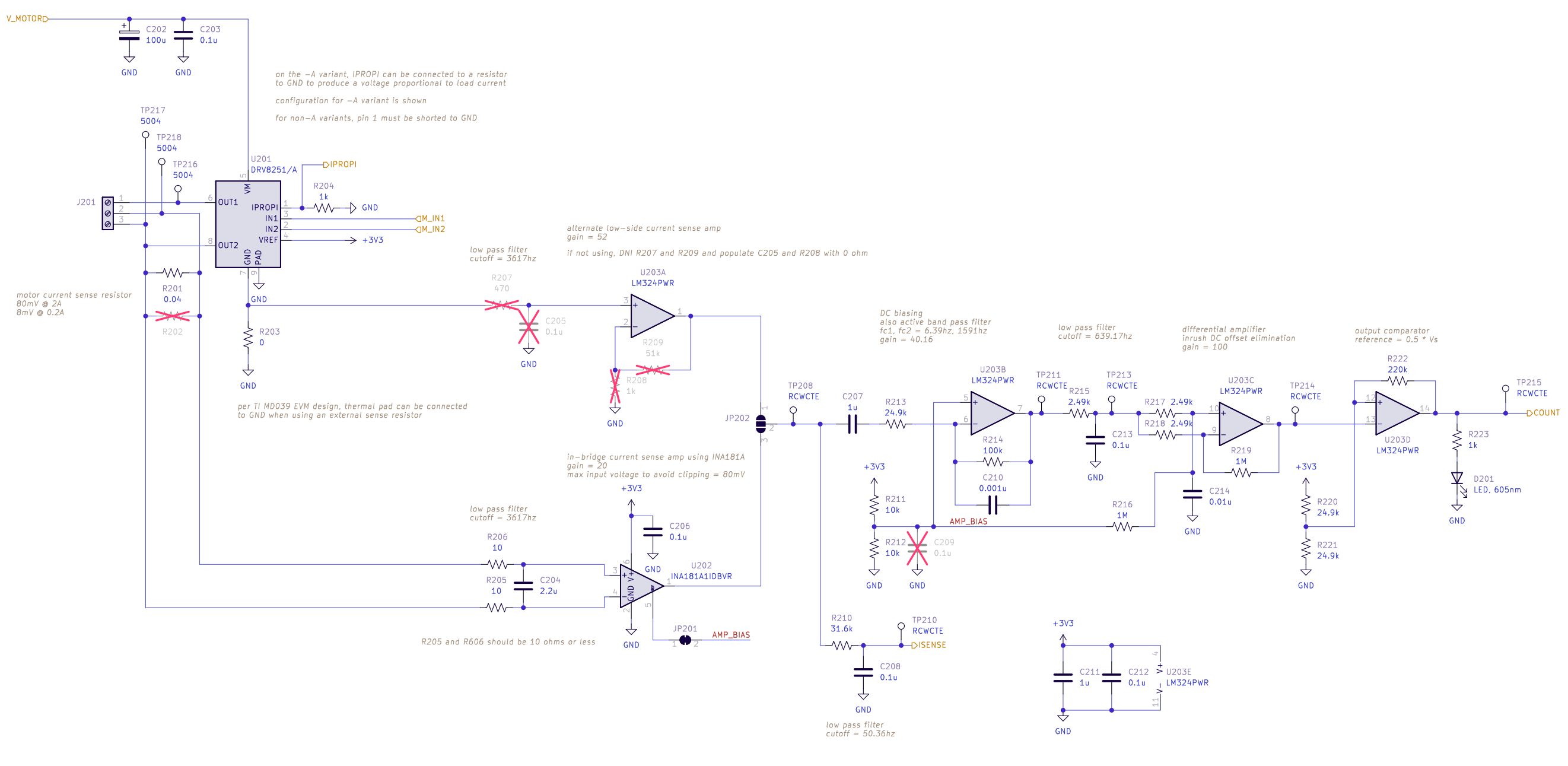
Schematic as PDF

The signal conditioning circuit is based on the designs described in Texas Instruments application note TIDA-01421 and Microchip application note AN3049. The initial current sense amplifier is implemented using the Texas Instruments INA181 IC (U202) with a current sense resistor directly in series with the motor, allowing for bidirectional current sensing. The remaining amplifier and filtering stages are implemented using an LM324 (U203) general-purpose quad op amp. U203B is used as an active bandpass filter, which works with two other RC low-pass filters to eliminate high frequency noise and low-frequency oscillations in current caused by varying load on the motor. U203C is used to subtract large and relatively slow changes in the signal, such as the motor's inrush current spike. U203D is used as a comparator with hysteresis to generate a clean output signal.
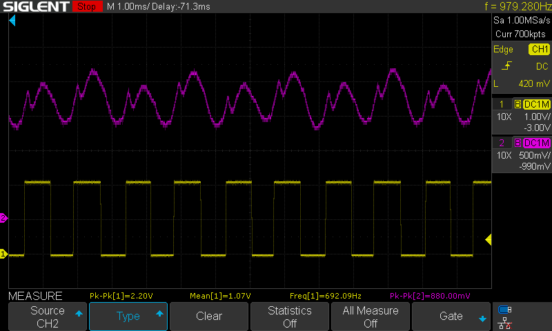
Purple: filtered, amplified motor current waveform (TP211); Yellow: output signal (TP215)

Design Modification Guide

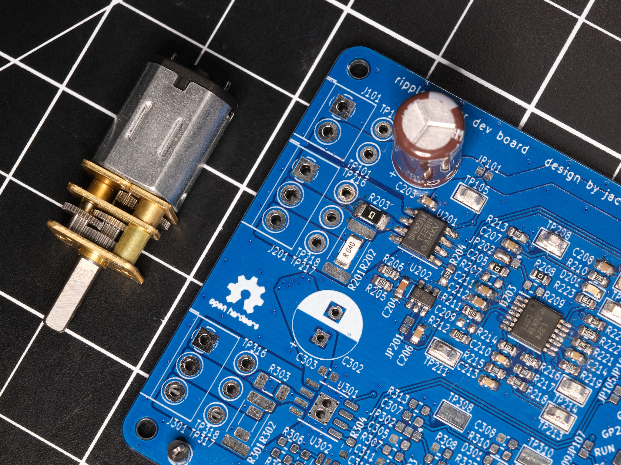
The component values used in this circuit will need to be adjusted for optimal performance with any motor - as-is, the values in the schematic were chosen for N20-size gearmotors and will work decently well for similar small motors.

When modifying the design for a different motor:

  • The current sense resistor (R201/R202) value and power rating must be selected to keep the power dissipation in the resistor well within its specified power rating. For larger motors with high inrush/stall current, the pulse load capability of the resistor should also be considered.
  • The current sense resistor value and the gain of the current sense amplifier (the INA181 IC used comes in four different fixed-gain options) must be selected to prevent clipping at the output of the current sense amplifier with maximum motor current: I_motor_max * R_isense * Gain < (3.3V / 2).

Several other components should be considered after choosing the sense resistor and amplifier:

  • The gain of the active bandpass filter, set by R213 and R214, should be selected experimentally to minimize clipping at the output of the filter (TP211).
  • The gain of the differential amplifier, set by R216-R219, should be selected experimentally to provide a clean output from the comparator (TP215). C214 should be changed if R217/R218 are changed by more than an order of magnitude.
  • The cutoff frequencies of the active bandpass filter and the RC low-pass filter formed by R215 and C213 may need to be changed depending on the speed of the motor used. It is recommended that the cutoff frequency of R215/C213 be at least the motor's ripple frequency at full speed and the cutoff frequency of R214/C210 be at least two times that frequency.

Development Board

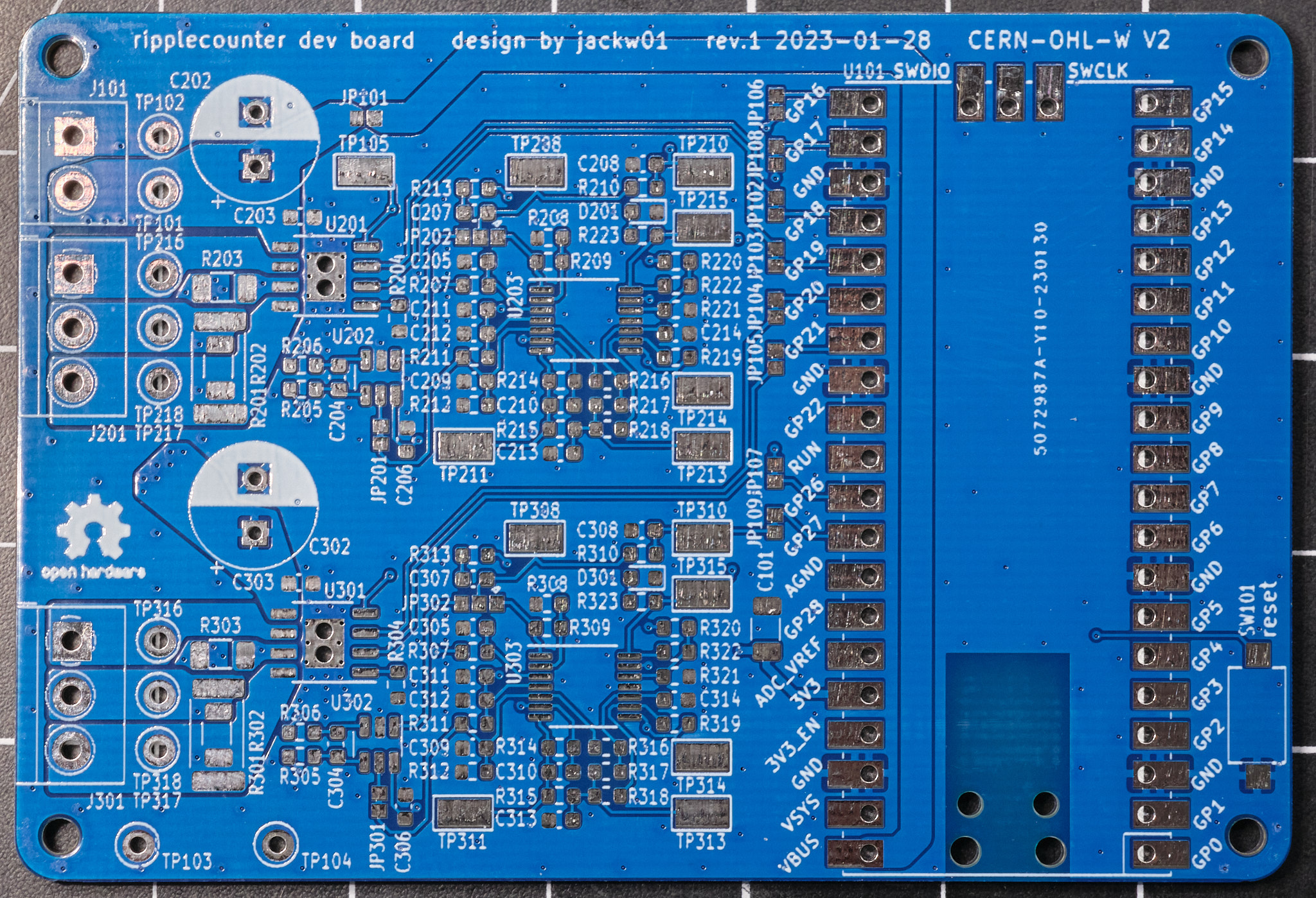
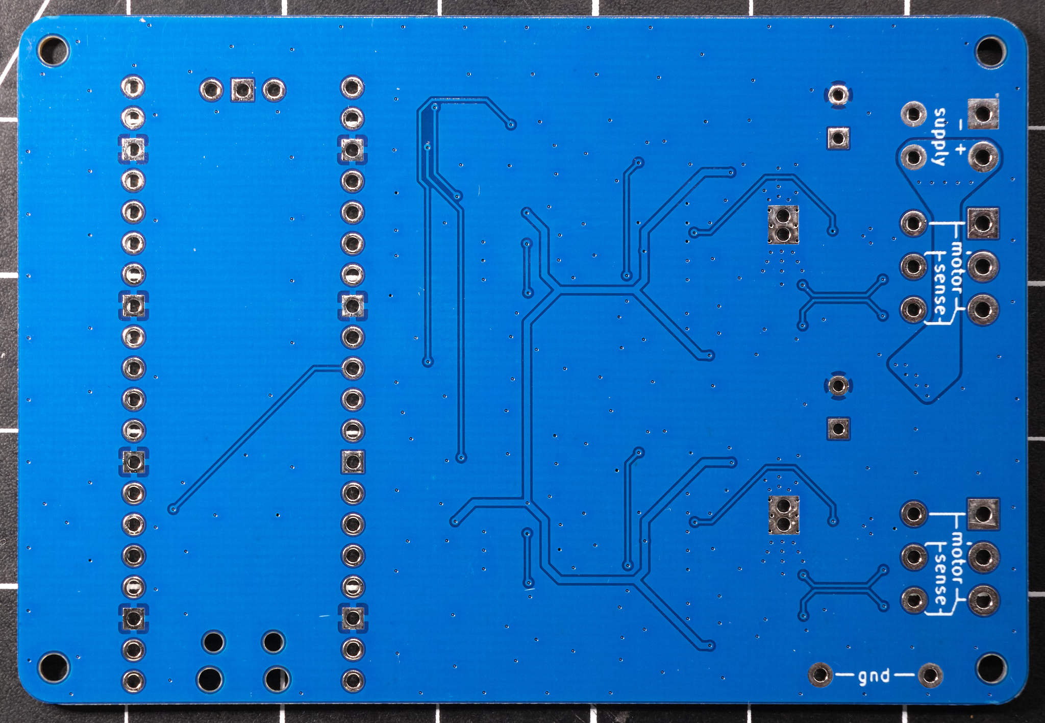
The ripplecounter development board incorporates a Raspberry Pi Pico microcontroller, two motor drivers, and two copies of the signal conditioning circuit. The board is designed to allow the use of Texas Instruments DRV8231, DRV8231A, DRV8251, or DRV8251A SO-8 package H-bridge motor driver ICs, for up to 50V motor supply voltage and 4.1A peak output current. An external motor driver may also be used. The development board is designed to be manufactured by any low-cost PCB supplier, such as JLCPCB or PCBWay, and easily assembled and modified by hand - the smallest passive components used are 0603 size.
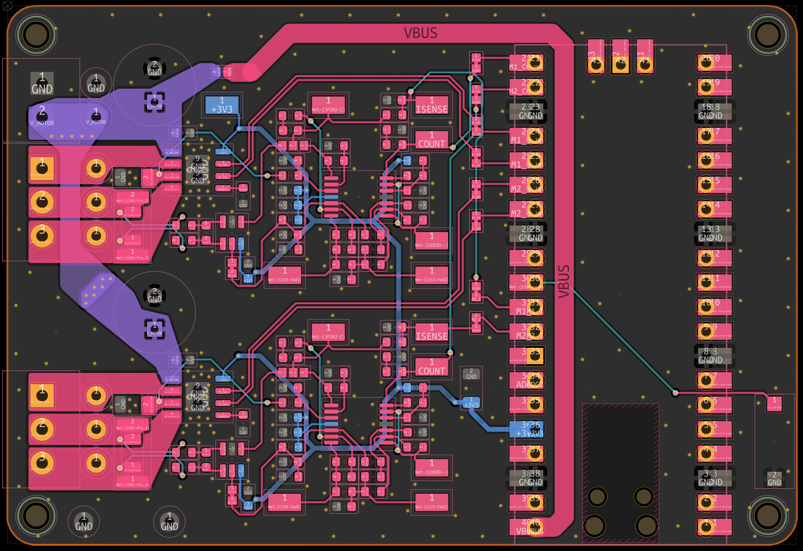
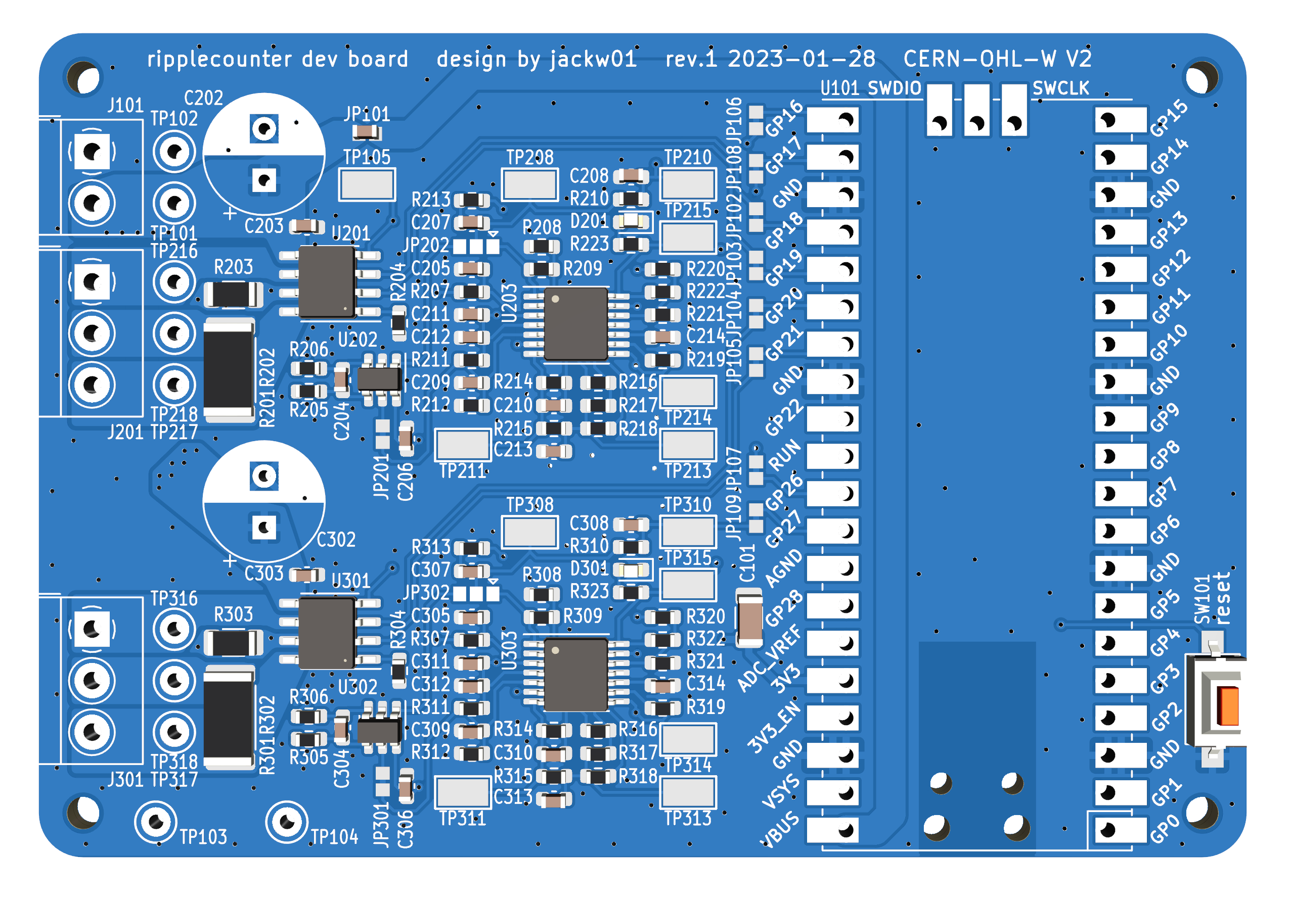
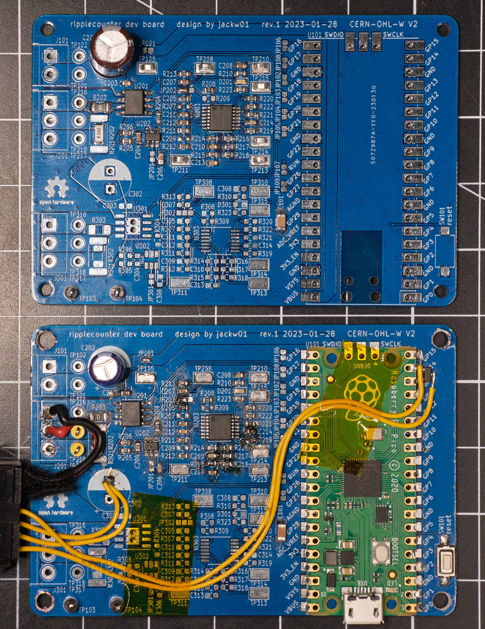
The top PCB is minimally assembled for manually testing the signal conditioning circuit; the bottom PCB has been modified to control a camera slider for focus stacking macrophotography.

License

The schematic is in the public domain - you are free to use this circuit design for any purpose, without attribution. The PCB layout and Gerber files for the development board are released under the CERN Open Hardware Licence Version 2 - Weakly Reciprocal (CERN-OHL-W V2).

Firmware

Basic firmware using the Raspberry Pi Pico C SDK is provided, which moves the motor while printing the position, speed, and current draw via UART. All important constants are documented in ripplecounter_motor.c.

Note: When used with the DRV8x21 motor controller on the development board, this firmware brakes the motor (as opposed to letting it coast) when it is not running, which is desirable for applications that require position control. If the motor is forcibly rotated while it is not running, the change in position will be detected via the ripple counter circuit, but sensing the direction of rotation is not implemented. If this functionality is needed, it can be implemented by sampling the motor current value read through the ADC, which will be negative or positive depending on which direction the motor is being turned.

License

All code provided is released under the MIT License.

Parts

126
QtyValueFootprintReferences
140.1uCapacitor_SMD:C_0603_1608MetricC203, C205, C206, C208, C209, C212, C213, C303, C305, C306, C308, C309, C312, C313
13RCWCTETestPoint:TestPoint_Keystone_5015_Micro-MinatureTP105, TP208, TP210, TP211, TP213, TP214, TP215, TP308, TP310, TP311, TP313, TP314, TP315
8~Custom:Jumper_0603_BridgedJP102, JP103, JP106, JP107, JP108, JP109, JP201, JP301
75004TestPoint:TestPoint_Keystone_5000-5004_MiniatureTP101, TP216, TP217, TP218, TP316, TP317, TP318
61kResistor_SMD:R_0603_1608MetricR204, R208, R223, R304, R308, R323
62.49kResistor_SMD:R_0603_1608MetricR215, R217, R218, R315, R317, R318
624.9kResistor_SMD:R_0603_1608MetricR213, R220, R221, R313, R320, R321
410Resistor_SMD:R_0603_1608MetricR205, R206, R305, R306
410kResistor_SMD:R_0603_1608MetricR211, R212, R311, R312
41MResistor_SMD:R_0603_1608MetricR216, R219, R316, R319
41uCapacitor_SMD:C_0603_1608MetricC207, C211, C307, C311
4~MountingHole:MountingHole_2.2mm_M2_ISO14580H101, H102, H103, H104
35001TestPoint:TestPoint_Keystone_5000-5004_MiniatureTP102, TP103, TP104
20Resistor_SMD:R_1206_3216MetricR203, R303
20.001uCapacitor_SMD:C_0603_1608MetricC210, C310
20.01uCapacitor_SMD:C_0603_1608MetricC214, C314
20.04Resistor_SMD:R_1206_3216MetricR201, R301
20603_ClosedCustom:Jumper_0603_BridgedJP104, JP105
2100kResistor_SMD:R_0603_1608MetricR214, R314
2100uCapacitor_THT:CP_Radial_D8.0mm_P3.50mmC202, C302
22.2uCapacitor_SMD:C_0603_1608MetricC204, C304
2220kResistor_SMD:R_0603_1608MetricR222, R322
231.6kResistor_SMD:R_0603_1608MetricR210, R310
2470Resistor_SMD:R_0603_1608MetricR207, R307
251kResistor_SMD:R_0603_1608MetricR209, R309
2DRV8251/ACustom:HSOP-8-1EP_3.9x4.9mm_P1.27mm_EP2.41x3.1mm_ThermalVias_HandSolderU201, U301
2INA181A1IDBVRPackage_TO_SOT_SMD:SOT-23-6U202, U302
2LED, 605nmLED_SMD:LED_0603_1608MetricD201, D301
2LM324PWRPackage_SO:TSSOP-14_4.4x5mm_P0.65mmU203, U303
2~Custom:Bi_0603_OpenJP202, JP302
2~TerminalBlock_4Ucon:TerminalBlock_4Ucon_1x03_P3.50mm_HorizontalJ201, J301
2~Resistor_SMD:R_2512_6332MetricR202, R302
110uCapacitor_SMD:C_1206_3216MetricC101
1PTS636 SM25 SMTR LFSButton_Switch_SMD:SW_SPST_CK_RS282G05A3SW101
1RPi PicoRPi_Pico:RPi_Pico_SMD_THU101
1~Custom:Jumper_0603JP101
1~TerminalBlock_4Ucon:TerminalBlock_4Ucon_1x02_P3.50mm_HorizontalJ101

Questions

How big is the Ripplecounter PCB?

It measures 82 × 56 mm and has 2 copper layers, 1.6 mm thick.

What parts does the Ripplecounter use?

126 parts, built around the DRV8251ADDA, INA181A1IDBVR(LX) and LM324PWRG. The full list of its parts is on this page, with links to each part's symbol and footprint where PCBKit's library has them.

Where can I download the Ripplecounter KiCad files?

From the jackw01/ripplecounter repository on GitHub, at the commit this page was made from: the board is pcb/ripplecounter.kicad_pcb and its schematic pcb/motordriver.kicad_sch. PCBKit opens the board in the browser, with nothing to install.

Can I use the Ripplecounter design in my own project?

Its repository states no licence, so its author keeps all rights: ask jackw01 before reusing the design.

Similar boards

  • 4 layers100 × 100 mmAmod m, the printed circuit board in 3D

    Amod m

    gallicchio/AMOD-and-RFMOD

    The tutorial's 2x12 adapter (/mudd/133electronics/icepi-zero-dac-adc/adapterboard/) with a 2 x 6 right-angle Pmod socket on a 15 mm extension of its right-hand end, so an Icepi Zero can drive AMOD-A's and RF-MOD's Pmod…

    207 parts
  • 4 layers263 × 139.8 mmLV Board Mk2, the printed circuit board in 3D

    LV Board Mk2

    Lafayette-Motorsports/LVBoards

    LV Board repository for Motorsports created 09.02.2025

    184 parts1
  • 2 layers100 × 84.7 mmMotorSignalConversion, the printed circuit board in 3D

    MotorSignalConversion

    WheelchairSeniorDesign/PCBs

    The PCB designs for the wheelchair for our senior design project

    30 parts1
  • 2 layers64 × 69.9 mmControl board, the printed circuit board in 3D

    Control board

    luckymuniza/spinkovacka

    64 parts
  • 2 layers65 × 56 mmFYDP, the printed circuit board in 3D

    FYDP

    Michael-Done/FYDP_ELEC

    Electrical schematic and layout for capstone design project.

    43 parts
  • 2 layers90 × 108 mmG5500-pidrive, the printed circuit board in 3D

    G5500-pidrive

    philcrump/g5500-pidrive

    Driving an AC Yaesu G-5500 Az+El with DC-source PWM from a Raspberry Pi.

    106 partsMIT
  • 4 layers57.8 × 80 mmArm drive, the printed circuit board in 3D

    Arm drive

    robotique-udes/PCB

    69 partsMIT
  • 4 layers140 × 140 mmPCU, the printed circuit board in 3D

    PCU

    Andresse2020/NovaDrone-Hardware

    Complete electronic system design for a high-performance quadcopter drone, developed entirely from scratch. Includes power distribution, motor control, flight stabilization, sensor integration, and communication…

    760 parts3