2 layers89 × 55.5 mm
Mintypcb
jackw01/pi-tin
Open source raspberry pi handheld retro gaming console
129 parts75CERN-OHL-W-2.0

 jackw01/pi-tin75
Open source raspberry pi handheld retro gaming console
Displaypcb is an open-source printed circuit board by jackw01, from the jackw01/pi-tin repository on GitHub, published under the CERN-OHL-W-2.0 licence. It is a 2-layer board of 39 × 46 mm with 33 parts on 47 nets, routed with 151 tracks and 28 vias.
It is built around the APX803-31SAG, CL21B106KPQNNNE and 62684-502100AHLF, with the BSS138BKW-TP among its other parts. Its parts include 5 resistors, 2 connectors, 1 capacitor, 1 IC and 1 transistor. It belongs with the retro computing and games boards of this library.


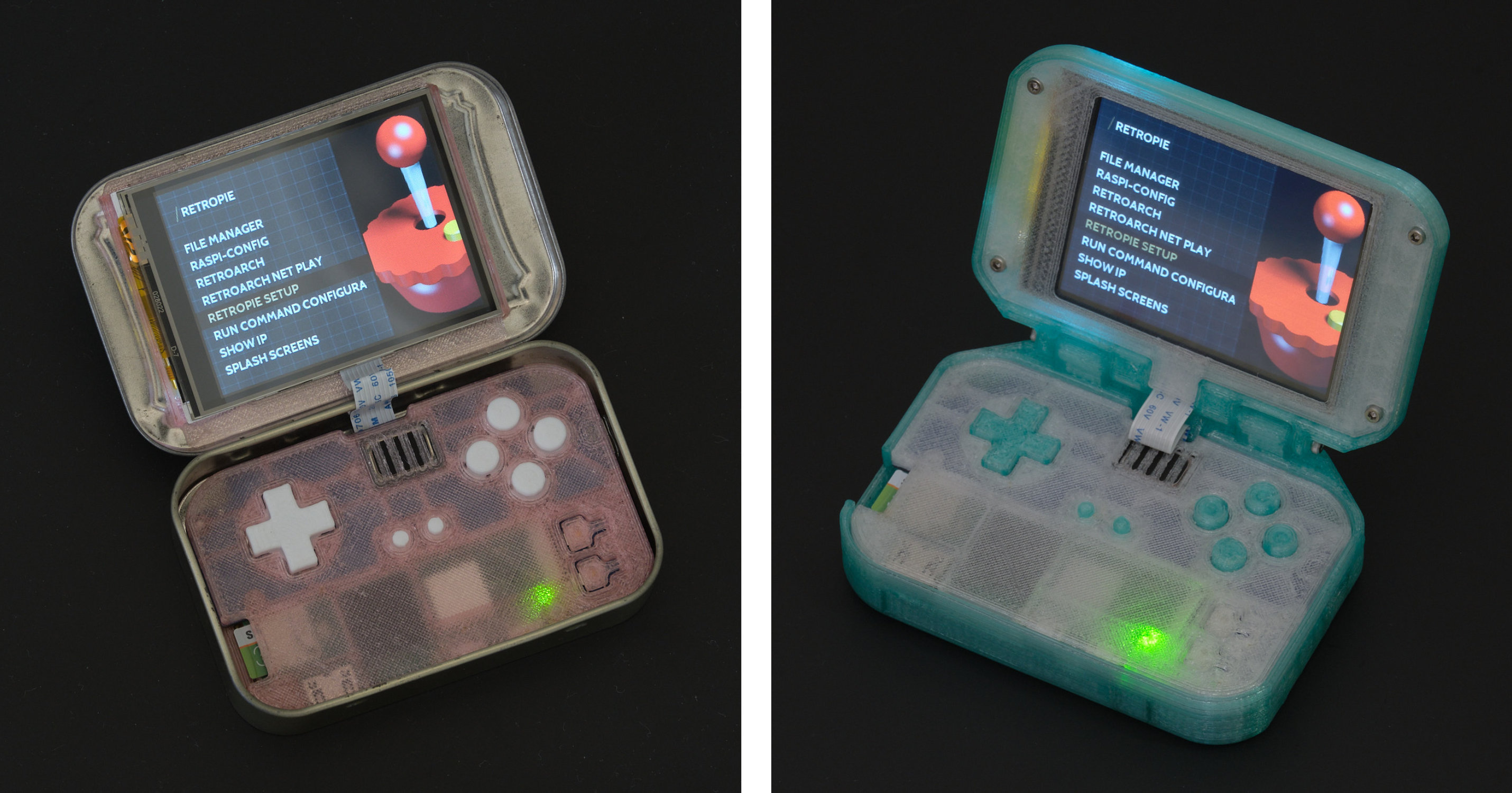
Kits are now available here!
Pi Tin is an open source retro gaming device designed around the Raspberry Pi Zero 2 W and a 2.8" 320x240 TFT display, the largest readily available size that will fit into an Altoids tin. The Pi Zero 2 W is capable of emulating most SNES, GBA, PS1, Genesis/Megadrive, and even some N64 games.
Pi Tin's gamepad uses the exact same Alps tactile switches and elastomer membrane design used in the Gameboy Advance SP and DSi to achieve superior button feel over designs using conductive rubber buttons or bare tactile switches. It features a soft power button to turn on or safely shut down the system with a single press, and is designed to be safe to use while charging and compatible with all USB-C cables and chargers. The battery lasts for up to 5 hours of gaming (tested on 3D printed case option - 2000mAh battery).
Building a Pi Tin requires a Raspberry Pi Zero 2 W, two custom PCBs, some 3D printed parts, and a few other components which are readily available from distributors. The PCBs require advanced soldering skills and ideally both a hot plate and hot air station to assemble by hand. We are working on making kits with assembled PCBs available to purchase.
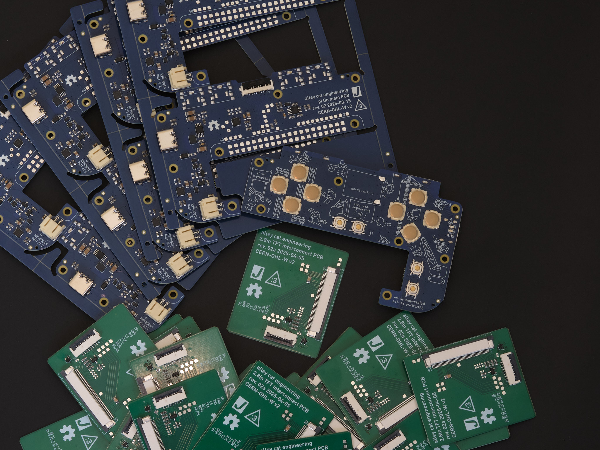
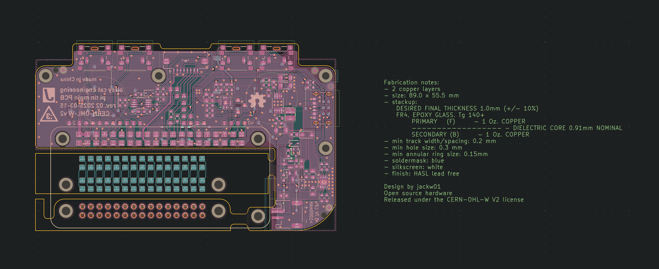
Main PCB Schematic as PDF (Rev. 2)
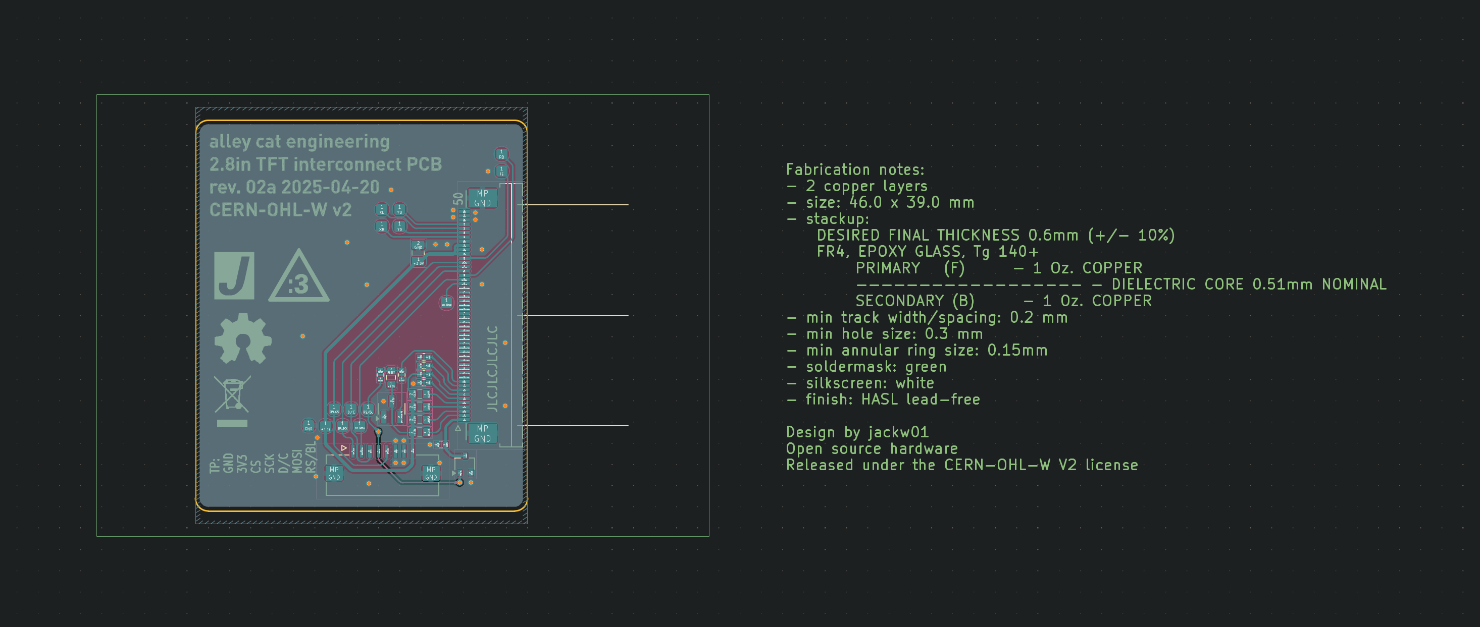
Display PCB Schematic as PDF (Rev. 2a)
Note 2025-06-07: Main PCB files have been updated with the practice boards included in the kits. Display PCB files have been updated to revision 2a with minor component changes and brightness control support. Previous revision files are in the old folder.
Note: Most other photos in this guide show Rev. 1 PCBs.
Pi Tin can either be built with a 3D printed clamshell case (93 x 66 x 26.5mm) or built to fit inside an Altoids tin.
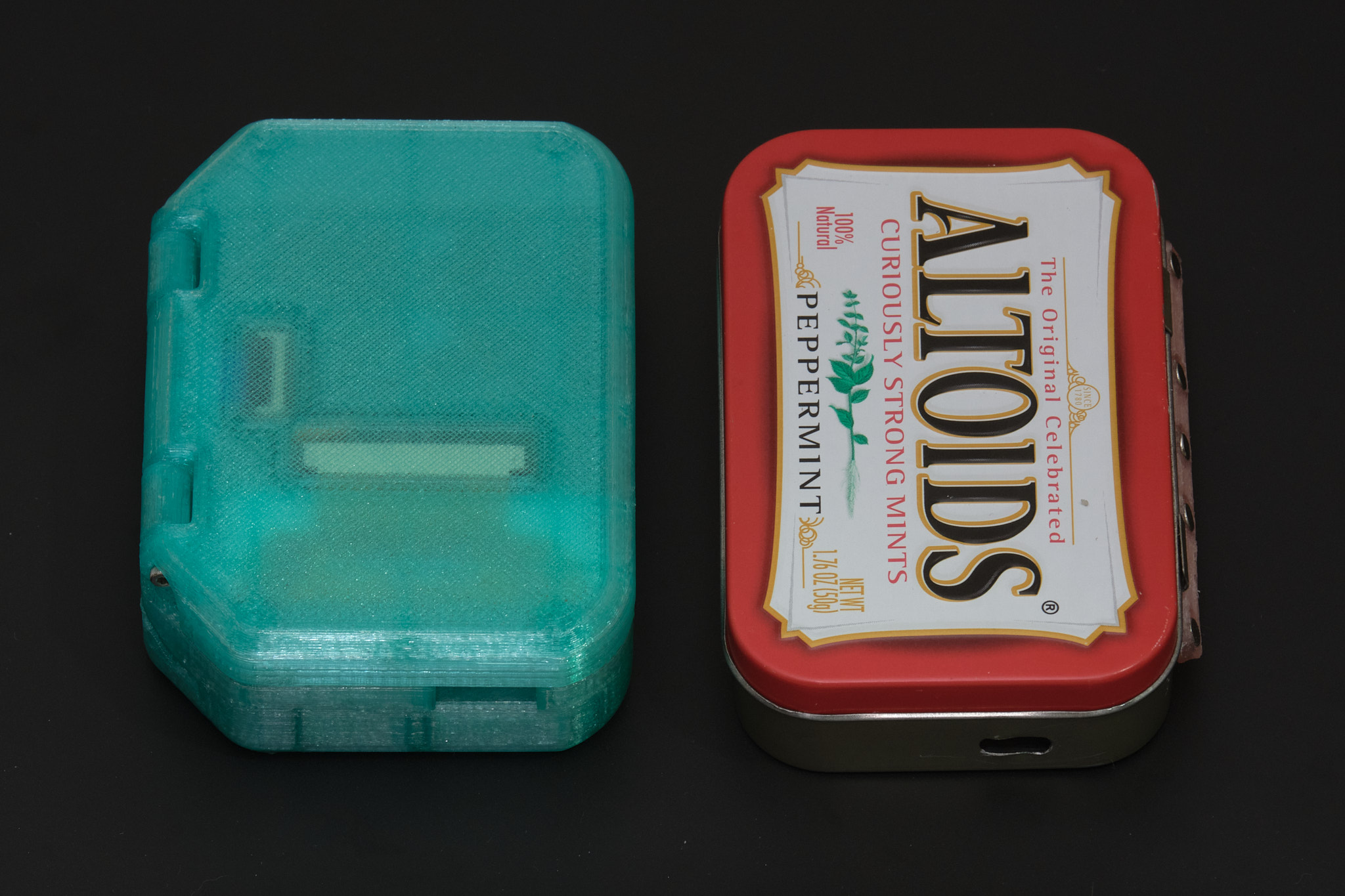
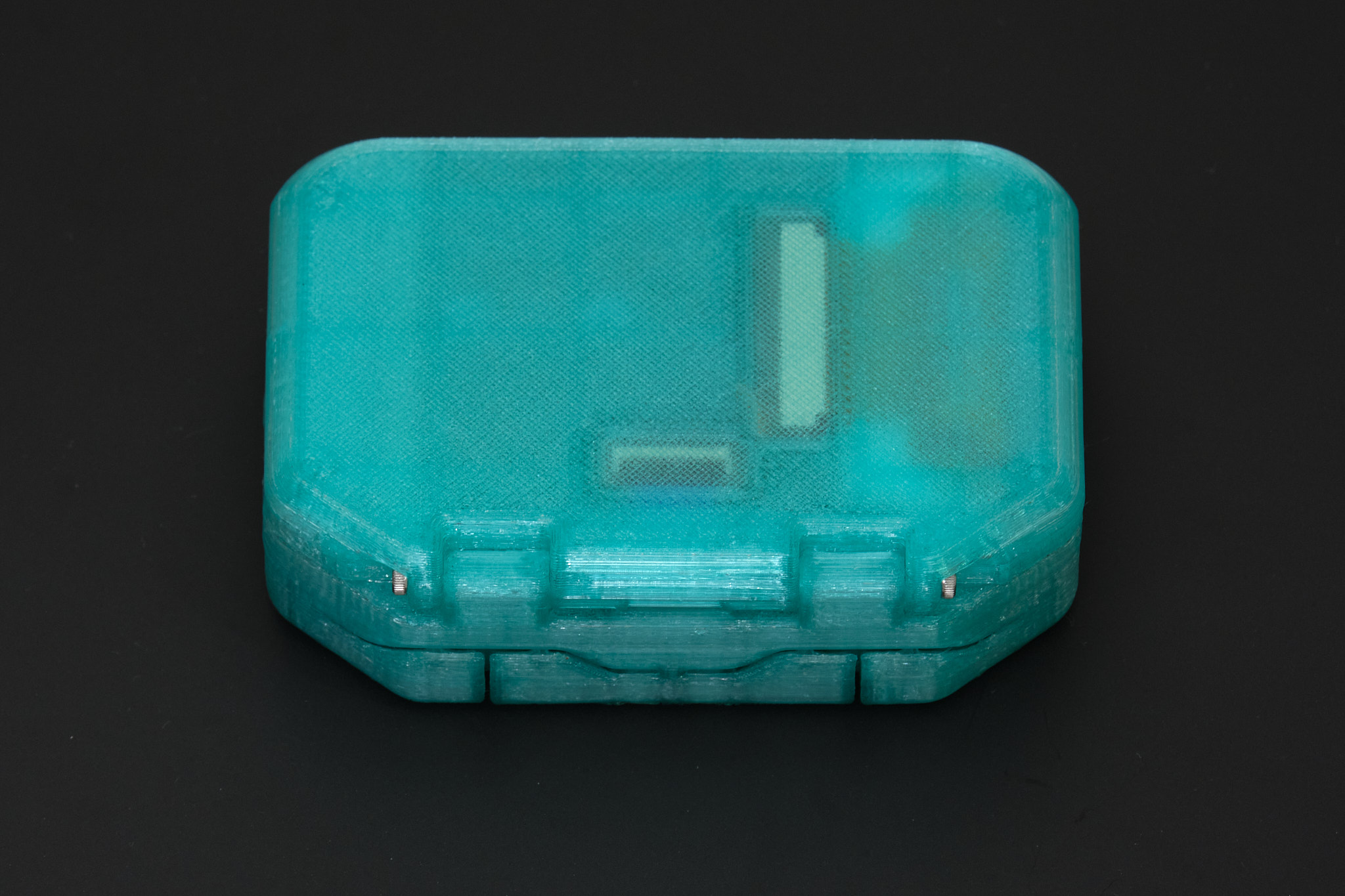
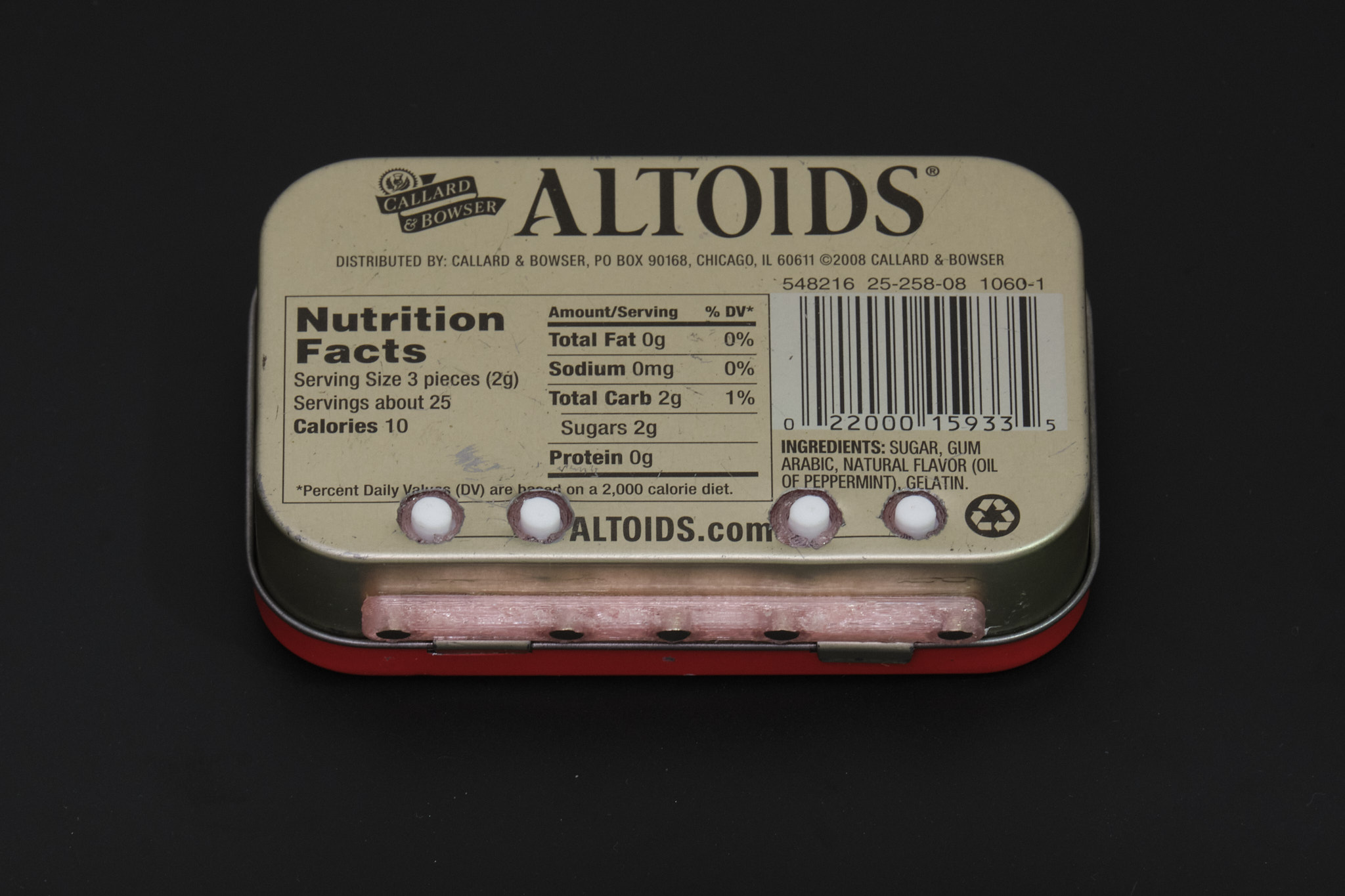
The Altoids tin build option is more difficult than the 3D printed case option; it requires additional tools and experience using them. It has poor ergonomics due to the constraints of building inside an Altoids tin and the battery capacity is 40% lower than the 3D printed case version. We strongly recommend the 3D printed case option for these reasons.
Important: Read through all the instructions thoroughly before building. This is an intermediate level project and we don't recommend attempting it without prior electronics kit building experience.
Build instructions for both options start with the hardware build guide.
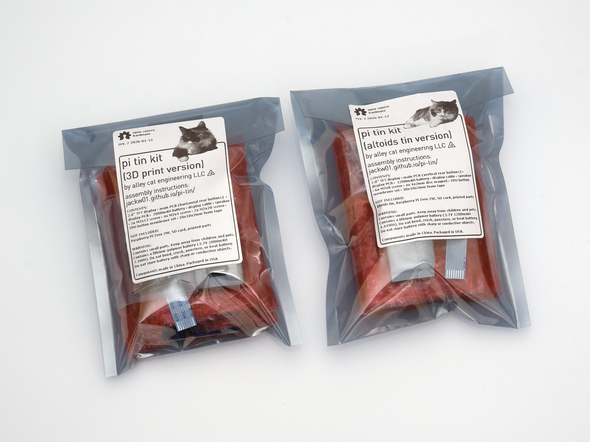
The source files for this project are located at https://github.com/jackw01/pi-tin/.
The PCB schematics, layouts, and Gerber files and the 3D CAD files for this project are released under the CERN Open Hardware Licence Version 2 - Weakly Reciprocal (CERN-OHL-W V2). The files in the software directory are in the public domain, free of copyright restrictions. The documentation for this project is released under the Creative Commons Attribution-ShareAlike 4.0 license.
We are aware of the existence of MintyPi; our main motivation for building this project was that MintyPi is no longer possible to build as it relies on proprietary parts that are not sold anymore. MintyPi was a closed-source commercial product and it was not released under a license limiting or requiring attribution for derivative works. The creators did not release a schematic of the custom PCBs or even documentation of what drivers/software were installed on their prebuilt SD card image.
Any trademarked product names found on this website belong to their respective owners; this project is in no way affiliated with or endorsed by these companies. Pi Tin is designed to run RetroPie, which is open source software released under the GPL. The prebuilt RetroPie disk image we provide does not contain any copyrighted ROMs or games. Pi Tin is not designed to enable illegal activity; we do not condone piracy and we will not provide support to anyone looking to obtain copyrighted content.
| Qty | Value | Footprint | References |
|---|---|---|---|
| 14 | TestPoint_Small | Custom:TestPoint_Pad_D1.5mm | TP101, TP102, TP103, TP104, TP105, TP106, TP107, TP108, TP109, TP110, TP111, TP112, TP113, TP114 |
| 6 | SolderJumper_2_Bridged | Custom:R_0402_1005Metric_bridged | JP101, JP102, JP103, JP104, JP105, JP106 |
| 4 | 10 | Resistor_SMD:R_0603_1608Metric | R101, R102, R103, R105 |
| 1 | 10k | Resistor_SMD:R_0603_1608Metric | R104 |
| 1 | 10u | Capacitor_SMD:C_0805_2012Metric | C101 |
| 1 | 2005280080 | Custom:Molex_200528-0080_1x08-1MP_P1.00mm_Horizontal | J102 |
| 1 | 62684-502100AHLF | Custom:AMPHENOL_62684-502100AHLF | J103 |
| 1 | APX803-31SAG | Package_TO_SOT_SMD:SOT-23 | U101 |
| 1 | BSS138 | Package_TO_SOT_SMD:SOT-323_SC-70 | Q101 |
| 1 | Display | Custom:TFT_2.8in_ILI9341 | N101 |
| 1 | SolderJumper_2_Open | Resistor_SMD:R_0402_1005Metric | JP107 |
The 32 most common of 33 parts.
It measures 39 × 46 mm and has 2 copper layers, 0.6 mm thick.
33 parts, built around the APX803-31SAG, CL21B106KPQNNNE, 62684-502100AHLF and BSS138BKW-TP. The full list of its parts is on this page, with links to each part's symbol and footprint where PCBKit's library has them.
From the jackw01/pi-tin repository on GitHub, at the commit this page was made from: the board is old/pcb_display_r2/displaypcb.kicad_pcb and its schematic old/pcb_display_r2/displaypcb.kicad_sch. PCBKit opens the board in the browser, with nothing to install.
Its repository publishes it under the CERN-OHL-W-2.0 licence: you may reuse it on that licence's terms (keep the author's notice, and for a copyleft licence share your changes alike).

SophBG/pi-tin-mod
Personal build of jackw01's Pi Tin (3D-printed clamshell version, KiCad 10). It adds 10 RGB LEDs under the buttons, a centred speaker, a USB-drive mode for the ROMs, and ESD protection on USB, and runs on an Orange Pi…

roman-koshchei/5ghz_wifibroadcast_hat
5GHz WiFibroadcast HAT for FPV video transmission, long-range comms, WFB-NG, network analysis and Monitor Mode

MostlyBuilds/speaker-pod-pcb
This is a PCB design for an ESP32-based speaker controller

ashfaque-ur-rahman/TI_MSPM0-PCB-Design
Texas Instruments MSPM0 microcontroller PCB design — KiCad 2-layer board based on Phil's Lab tutorial


EthanGreenhouse/rng-pcb
NE555 + CD4017 random number generator. 41-component SMD board, no microcontroller.

jrseti/Dish
Simple controller with toggle switches to move the dish motors

jrseti/roboclaw-cm4-dc-dish-controller
Satellite dish controller using a ROBOCLAW-2X15A-OEM controlled by a Raspberry Pi CM4 module. Powered by DC battery.
