Skip to the content
PCBKitNew board
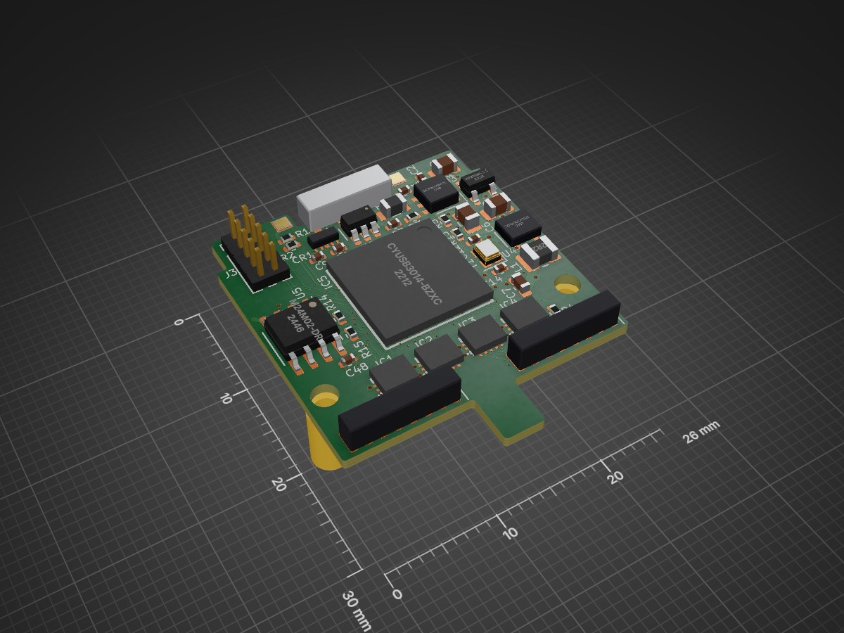
4 layers26 × 30 mmFramework logic analyzer, the printed circuit board in 3D

16 channel USB 3 Logic analyzer expansion card for Framework laptop

Size
26 × 30 mm
Copper layers
4
Thickness
1 mm
Parts
93
Nets
145
Pads
441
Tracks, vias
1,144, 196
Pours
6
Routed
Yes
KiCad
KiCad 7 (file 20221018)
Created
20 Apr 2023
Updated
16 Mar 2024

Overview

Framework logic analyzer is an open-source printed circuit board by JackToaster, from the JackToaster/framework_logic_analyzer repository on GitHub. It is a 4-layer board of 26 × 30 mm with 93 parts on 145 nets, routed with 1,144 tracks and 196 vias.

It is built around the CYUSB3014-BZXC, SC189CSKTRT and TXU0104QWBQARQ1, with the AP2112K-3.3, MMBT3904 and BLM21PG221SN1D among its other parts. Its parts include 47 capacitors, 15 resistors, 10 ICs, 4 connectors and 3 transistors. It belongs with the sensors and measurement boards of this library.

Main components

7

Parts

93
QtyValueFootprintReferences
23100nCapacitor_SMD:C_0402_1005MetricC3, C10, C13, C15, C16, C17, C18, C20, C22, C24, C27, C29, C31, C32, C34, C36 +7
910nCapacitor_SMD:C_0402_1005MetricC28, C30, C33, C35, C38, C40, C42, C44, C46
622uCapacitor_SMD:C_0603_1608MetricC7, C19, C21, C23, C25, C26
41kResistor_SMD:R_0402_1005MetricR6, R10, R11, R12
4MPZ2012S601AInductor_SMD:L_0805_2012MetricFB2, FB3, FB4, FB5
4TXU0104QWBQARQ1TXU0104:TXU0104QWBQARQ1IC1, IC2, IC3, IC4
4TestPointTestPoint:TestPoint_Pad_1.5x1.5mmTP1, TP2, TP3, TP4
310uFCapacitor_SMD:C_0805_2012MetricC4, C5, C6
32kResistor_SMD:R_0402_1005MetricR7, R14, R15
3MMBT3904Package_TO_SOT_SMD:SOT-23Q1, Q2, Q3
2100n 25VCapacitor_SMD:C_0402_1005MetricC8, C9
210pCapacitor_SMD:C_0402_1005MetricC12, C14
21uCapacitor_SMD:C_0402_1005MetricC1, C2
25.1kResistor_SMD:R_0402_1005MetricR1, R2
2Conn_02x08_Odd_Even20021311-00016T4LF:20021311-00016T4LFJ1, J2
2MountingHoleMountingHole:MountingHole_2.2mm_M2H1, H2
1100kResistor_SMD:R_0402_1005MetricR13
110kResistor_SMD:R_0402_1005MetricR5
119.200 MHzCrystal:Crystal_SMD_2016-4Pin_2.0x1.6mmY1
12.2uInductor_SMD:L_1008_2520MetricL1
1200R 1%Resistor_SMD:R_0402_1005MetricR3
1270Resistor_SMD:R_0402_1005MetricR9
1560Resistor_SMD:R_0402_1005MetricR8
16.04k 1%Resistor_SMD:R_0402_1005MetricR4
1AP2112K-3.3Package_TO_SOT_SMD:SOT-23-5U3
1BLM21PG221SN1DInductor_SMD:L_0805_2012MetricFB1
1CYUSB3014-BZXCCYUSB301X:BGA121C80P11X11_1000X1000X120IC5
1Conn_ARM_JTAG_SWD_10Connector_PinHeader_1.27mm:PinHeader_2x05_P1.27mm_VerticalJ3
1M24M02-DRPackage_SO:SOIC-8_3.9x4.9mm_P1.27mmU5
1NCP360SNT1GNCP360:TSOP5_3X1P5_ONSU1
1SC189CSKTRTSC189:SOT_CSKTRT_SEMU4
1SP3010-04UTGSP3010:UDFEN-10_MO229_LTFCR1
1USB_C_PlugExpansion_Card:USB_C_Plug_Molex_105444P1
1WE-TVS-82400102Package_TO_SOT_SMD:SOT-23-6U2

Questions

How big is the Framework logic analyzer PCB?

It measures 26 × 30 mm and has 4 copper layers, 1 mm thick.

What parts does the Framework logic analyzer use?

93 parts, built around the CYUSB3014-BZXC, SC189CSKTRT, TXU0104QWBQARQ1 and AP2112K-3.3. The full list of its parts is on this page, with links to each part's symbol and footprint where PCBKit's library has them.

Where can I download the Framework logic analyzer KiCad files?

From the JackToaster/framework_logic_analyzer repository on GitHub, at the commit this page was made from: the board is framework_logic_analyzer.kicad_pcb and its schematic USB3.kicad_sch. PCBKit opens the board in the browser, with nothing to install.

Can I use the Framework logic analyzer design in my own project?

Its repository states no licence, so its author keeps all rights: ask JackToaster before reusing the design.

Similar boards

  • 6 layers90 × 147.7 mmImx477, the printed circuit board in 3D

    Imx477

    wzwqoo/fmcw_10ghz_radar

    A single-board 1TX / 3RX, 10 GHz FMCW radar, its Artix-7 range–Doppler–CFAR backend, and the carrier board that mounts the radar alongside a global-shutter camera and an impact microphone.

    123 parts
  • 4 layers69.9 × 19 mmCar display v3, the printed circuit board in 3D

    Car display v3

    jsandmeyer/camaro-aftermarket-radio-aux-display

    Temperature and Reverse Sensor Display for Gen5 Camaro with Aftermarket Radio and Trims

    48 partsMIT
  • 6 layers40 × 15 mmMiniDAQ, the printed circuit board in 3D

    MiniDAQ

    Aharoni-Lab/MiniDAQ

    Simplified bare bones DAQ for Miniscopes and Minicams

    162 parts
  • 6 layers59 × 62 mmDigiRED v1.0, the printed circuit board in 3D

    DigiRED v1.0

    myriadrf/RASDR

    Radio Astronomy Software Defined Radio

    538 parts62
  • 4 layers70 × 92.8 mmFE 8CH, the printed circuit board in 3D

    FE 8CH

    osqzss/PocketSDR

    The Pocket SDR FE device includes 2, 4, or 8 RF frontend channels, supporting the GNSS L1 band (1525 - 1610 MHz) or L2/L5/L6 bands (1160 - 1290 MHz). For these signal bands, refer to GNSS Signal Bands.

    238 parts17
  • 6 layers50 × 50 mmVoyager logic, the printed circuit board in 3D

    Voyager logic

    joshajohnson/voyager-logic

    FX3 based logic analyser

    159 parts2
  • 8 layers50 × 50 mmFpga board, the printed circuit board in 3D

    Fpga board

    Scrarf/PCB_For_FPGA_Path_Tracer

    A PCB for FPGA Path tracer project.

    206 parts1